2-12
BRC-300/300P
BRU-300/300P
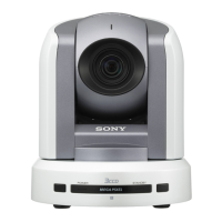
CN805
CN806
PSW
2.6 x 6
PSW
2.6 x 6
EXP chassis assembly
2-2. BRC-300/300P PC Boards
n
Tighten the screws as following torque.
PSW2.5/PSW2.6 screws: 26.0 x 10
_2
N.m
B2/BTP2/PSW2 screws: 18.0 x 10
_2
N.m
2-2-1. CC-91 Board
Removing
1. Remove the base plate. (Refer to Section 1-3-4.)
2. Remove the SY-314 board.
(Refer to steps 2 to 4 in Section 2-2-11.)
3. Remove the blank panel. (Refer to Section 1-3-5.)
4. Remove the four screws, and disconnect the flexible
flat cables from the connectors (CN805, CN806) on
the CC-91 board, then remove the EXP chassis
assembly.
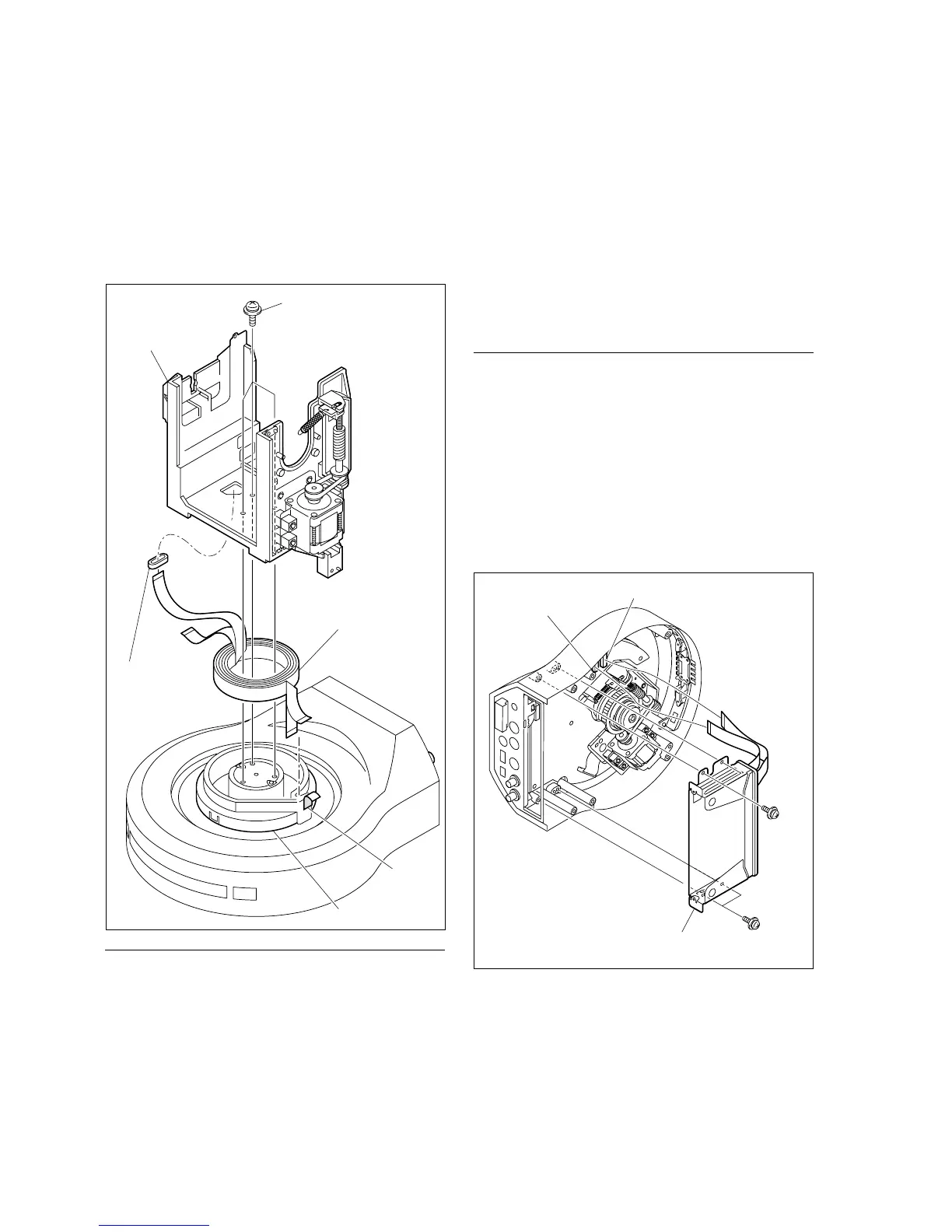
15. Remove the three screws, and remove the tilt chassis
assembly.
16. Remove the ferrite bead from the combined flexible
flat cable.
17. Remove the tape A, and remove the combined flexible
flat cable from the pan FFC cover.
Installation
18. Reattach the combined flexible flat cable in the reverse
order from steps 12 to 17.
n
Replace the tapes A with new ones.
19. Reassemble the unit in the reverse order from steps 1
to 11.
PSW2.6 x 6
Pan FFC cover
Tape A
Tilt chassis
Combined flexible flat cable
Ferrite bead