3-30
BRC-300/300P
BRU-300/300P
White
A
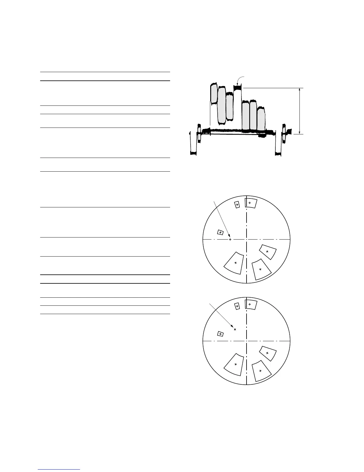
Fig. 3-2-1.
Fig. 3-2-2.
<For NTSC model>
<For PAL model>
B-Y
R-Y
Mg
R
YL
G
B
Cy
Burst positon
B-Y
R-Y
Burst positon
YL
R
G
B
Cy
Mg
3-2. BRC-300/300P Camera Block Electrical Alignment
Adjusting procedure
Order Page Address Data Procedure
1 Check that the picture frame is
set to the specified position.
(Refer to “3-2-13. Picture Frame
Setting”.)
2 0 01 01 Set the data.
3 6 01 3D Set the data, and press
PAUSE button.
4 6 9D Change the data so that the
white level is the following level.
(Fig. 3-2-1.)
A = 642.6 mV (NTSC)
A = 630 mV (PAL)
5 6 01 61 Set the data, and press
PAUSE button.
6 6 02 Check that the data changes to
“01”.
n
The adjustment data will be
automatically input to page: F,
addresses: 38 to 3B.
7 Adjust the GAIN and PHASE of
the vectorscope, and adjust the
burst luminance point to the
burst position of the color
reproduction frame. (Fig. 3-2-2.)
8 Check that all color luminance
points settle within each color
reproduction frame. (Fig 3-2-2.)
Settings after adjustment
Order Page Address Data Procedure
1 6 01 00 Set the data, and press PAUSE
button.
2 6 9D 00 Set the data.
3 0 01 00 Set the data.
 Loading...