Chapter 2 Location and Function of Parts
2-2 Chapter 2 Location and Function of Parts
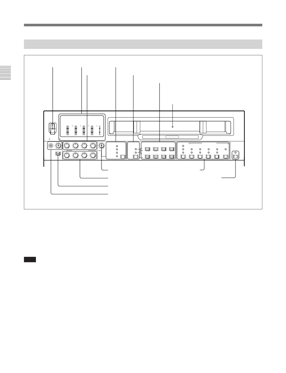
2-1 Control Panels
-20
PHONES
DISPLAY
FULL/FINE
CH-1 CH-2 CH-3 CH-4 VIDEO
POWER
REC
PULL FOR VARIABLE
PB
ON
OFF
-80
-20
-30
-40
-10
0
dB
-80
-20
-30
-40
-10
0
dB
-80
-30
-40
-10
0
dB
-80
-20
-30
-40
-10
0
dB
0
-2
2
-4
COMPOSITE
COMPONENT
(Y-R,B)
SDI
VIDEO INPUT SELECT AUDIO INPUT/MONITOR SELECT
INPUT
L
R
CH-1 CH-2 CH-3 CH-4
LTC
TC
AUTO
VITC
INT
EXT
PRESET
REGEN
FREE
RUN
REC
RUN
DEF
NDF
ON
9P
TC GENERATOR
VITC
ANALOG /
REMOTE
/LOCAL
SDDI
(VIDEO&AUDIO)
MONITOR
DIGITAL
HIGH SPEED
SDI
ANALOG/
AES/EBU
1 POWER
switch
2 Level meters
3 REC controls
4 VIDEO INPUT SELECT switch and indicators
5 Audio selection function selector switch and indicators
6 AUDIO INPUT/MONITOR SELECT buttons
(Before Version 2.00)
AUDIO INPUT/MIXING/MONITOR SELECT
buttons (Version 2.00 or later)
7 VIDEO control
8 PB controls
9 DISPLAY FULL/FINE switch
0 PHONES jack and control
!¡ Time code setting section
!™ REMOTE/LOCAL switch and indicator
1 POWER switch
This powers the unit on and off. When the unit is
powered on, the level meters 2 and the fluorescent
display in the lower control panel light.
To power the unit off, press the side of the POWER
switch marked “OFF”.
Note
After carrying out operations on this unit using the
hard disk, before powering the unit off be sure to press
the EJECT button (see page 2-17) to close the files on
the hard disk. Powering off the unit with files left
open may result in a loss of system data from the hard
disk.
2 Level meters
These show the audio levels of channels 1 to 4
(recording levels in recording mode or E-E mode
1)
and
playback level in playback mode) and the video levels
of input composite video signals.
There are two modes for audio level indications:
FULL and FINE, selected by the DISPLAY FULL/
FINE switch 9.
..........................................................................................................................................................................................................
1) E-E mode: Abbreviation of “Electric-to-Electric mode.”
In this mode, video and audio signals input to the VTR
are output after passing through internal electric circuits,
but not through magnetic conversion circuits such as
heads and tapes. This can be used to check input signals
and for adjusting input signal levels.
Cassette compartment
2-1-1 Upper Control Panel