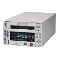
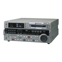
Chapter 2 Location and Function of Parts
Chapter 2 Location and Function of Parts 2-23
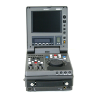
75Ω
ON
OFF
75Ω
ON
OFF
VIDEO INPUT VIDEO OUTPUT
REF.VIDEO COMPOSITE COMPONENT
(OPTION) (OPTION)
Y
R-Y
B-Y
COMPONENT
(OPTION)
Y
R-Y
B-Y
1
2
3
COMPOSITE
(SUPER)
ALTERNATIVE
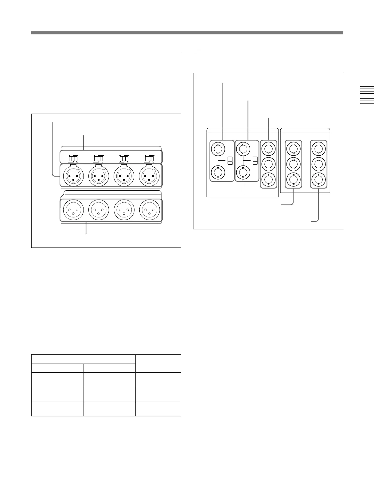
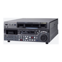
1 Analog (digital: option) audio input/
output section
In the standard version this is an analog audio input/
output section. By means of an option, you can
replace it by AES/EBU digital audio inputs and
outputs.
1 AUDIO INPUT CH1 to CH4 (channels 1 to 4)
connectors (XLR 3-pin, female)
Input analog audio signals to channels 1 to 4.
2 AUDIO INPUT CH1 to CH4 (channels 1 to 4)
LEVEL switches
Set these for each channel as shown in the following
table, according to the audio input levels to the
AUDIO INPUT CH1 to CH4 connectors and the
impedance.
AUDIO INPUT CH1 to CH4 LEVEL switch settings
3 AUDIO OUTPUT CH1 to CH4 connectors
(XLR 3-pin, male)
These output analog audio signals for channels 1 to 4.
3 AUDIO OUTPUT CH1 to CH4
connectors
2 Analog video input/output section
1 REF. (reference) VIDEO INPUT connectors
(BNC type) and 75 Ω termination switch
Input a reference video signal. Input a video signal
with chroma burst (VBS) or a monochrome video
signal (VS). When using the loop-through connection
set the switch to the OFF position, and otherwise to the
ON position.
2 COMPOSITE VIDEO INPUT connectors (BNC
type) and 75 Ω termination switch
Input analog composite video signals.
When using the loop-through connection set the switch
to the OFF position, and otherwise to the ON position.
Of these and the COMPONENT VIDEO INPUT
connectors 3, only one set can be used, according to
an option.
To use these connectors requires the BKDW-505 (for
DNW-A100/A50/A45) or BKDW-506 (for DNW-
A100P/A50P/A45P) option.
3 COMPONENT VIDEO INPUT connectors
(BNC type)
Input analog component video signals (Y/R–Y/B–Y).
Of these and the COMPOSITE VIDEO INPUT
connectors 2, only one set can be used, according to
an option.
To use these connectors requires the BKDW-104
option.
4 COMPOSITE VIDEO OUTPUT
connectors
1 AUDIO INPUT CH1 to CH4 connectors
2 AUDIO INPUT CH1 to CH4 LEVEL
switches
1 REF. VIDEO INPUT connectors and 75 Ω
termination switch
2 COMPOSITE VIDEO INPUT connectors
and 75 Ω termination switch
3 COMPONENT VIDEO INPUT
connectors
AUDIO INPUT
AUDIO OUTPUT
600Ω
LOW HIGH
OFF ON
CH1
LEVEL
600Ω
LOW HIGH
OFF ON
CH4
LEVEL
600Ω
LOW HIGH
OFF ON
CH3
LEVEL
600Ω
LOW HIGH
OFF ON
CH2
LEVEL
CH1 CH2 CH3 CH4
Audio input level and impedance Switch setting
Level
–60 dBu
(microphone input)
LOW-OFF
(left position)
+4 dBu
(line audio input)
HIGH-OFF
(center position)
+4 dBm
(line audio input)
HIGH-ON 600 Ω
(right position)
600 Ω
High impedance
(approx. 20 kΩ)
Impedance
High impedance
(approx. 20 kΩ)
5 COMPONENT VIDEO OUTPUT connectors