Chapter 2 Location and Function of Parts
Chapter 2 Location and Function of Parts 2-25
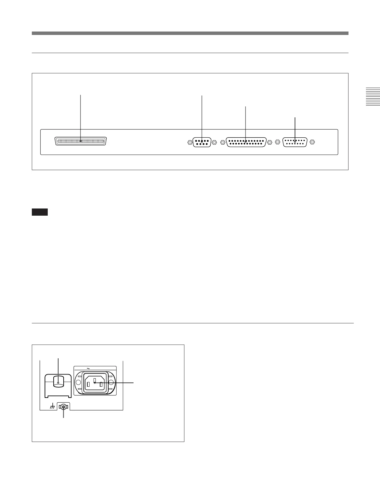
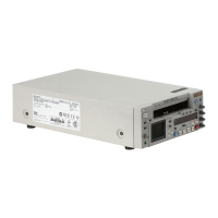
SCSI REMOTE(9P) RS-232C VIDEO CONTROL
5 External device connectors
1 SCSI connector (68-pin)
Use this for connection to another device supporting
SCSI 2.
Note
If this connector is not used, be sure to attach a SCSI
terminator. If no SCSI terminator is attached, the hard
disk may malfunction.
2 REMOTE (9P) connector (D-subminiature 9-
pin)
For editing with two DNW-A100/A100P units, or with
another D-1, D-2, or Betacam VTR controlled by a
BVE-series editor such as a BVE-900/910/2000/9000/
9000P/9100/9100P, use a 9-pin remote control cable
for connection to the other device.
3 RS-232C connector (D-subminiature 25-pin)
Use this for monitoring and diagnosis of the state of
this unit from an external computer, using ISR
(Interactive Status Reporting).
4 VIDEO CONTROL connector (D-subminiature
15-pin)
For remote control of the internal digital video
processor, connect an optional BVR-50/50P Remote
Control Unit or similar.
Always power off this unit before connecting the
remote control unit.
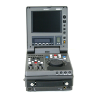
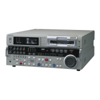
6 Power supply section
1 AC IN connector
2 BREAKER button
1 AC IN connector
Use the supplied power cord to connect this to an AC
outlet.
2 BREAKER button
This jumps out if an excess current flows on the
primary side of the AC power circuit.
3 Ground terminal
Connect this to ground.
1 SCSI connector
2 REMOTE (9P) connector
3 RS-232C connector
4 VIDEO CONTROL
connector
AC IN
BREAKER
3 Ground terminal