Chapter 2 Location and Function of Parts
2-24 Chapter 2 Location and Function of Parts
2-2 Connector Panel
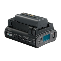
4 Time code input/output section and
audio monitor signal output section
1 TIME CODE IN connector (XLR 3-pin, female)
To record time code from an external device, input a
time code signal from the time code output connector
of the other device.
2 TIME CODE OUT connector (XLR 3-pin, male)
This outputs a time code according to the operating
state of the unit, as follows:
•During playback: the playback time code
By setting extended menu item 606, you can also
output the time code from the internal time code
generator locked to the playback time code..
•During recording: the time code generated by the
internal time code generator or the time code input to
the TIME CODE IN connector.
3 MONITOR OUTPUT connectors (XLR 3-pin,
male)
According to the setting of the AUDIO INPUT /
MONITOR SELECT buttons (Before Version 2.00) or
the AUDIO INPUT/MIXING/MONITOR SELECT
buttons (Version 2.00 or later) on the upper control
panel, two (L and R) audio monitor signals are output.
TIME CODE
MONITOR OUTPUT
IN OUT
RL
4 COMPOSITE VIDEO OUTPUT connectors
(BNC type)
These output analog composite video signals.
When the CHARACTER switch on the subsidiary
control panel is set to ON, the output from connector 3
(SUPER) has superimposed text information such as
time code, menu settings, and alarm messages.
5 COMPONENT VIDEO OUTPUT connectors
(BNC type)
These output analog component video signals (Y/R–Y/
B–Y).
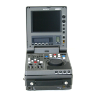
3 Digital input/output section
1 SDDI (Serial Digital Data Interface) DIGITAL
INPUT connector (BNC type) (DNW-A100/A100P
only)
Input SDDI format digital video/audio signals. This
connector can only be used when the optional SDDI
input board is installed.
2 SDI (Serial Digital Interface) DIGITAL INPUT
connectors (BNC type)
Input D1 format digital video/audio signals. Of the
two connectors, the upper one is for input, and the
lower one is for a active-through connection.
3 SDDI (Serial Digital Data Interface) DIGITAL
OUTPUT connectors (BNC type) (DNW-A100/
A100P only)
These output SDDI format digital video/audio signals.
4 SDI (Serial Digital Interface) DIGITAL
OUTPUT connectors (BNC type)
These output D1 format digital video/audio signals.
DIGITAL INPUT
SDDI
(OPTION)
SDI SDDI SDI
DIGITAL OUTPUT
1
2
1
2
1 SDDI DIGITAL INPUT connector (DNW-A100/A100P
only)
2 SDI DIGITAL INPUT connectors
3 SDDI DIGITAL OUTPUT
connectors (DNW-A100/A100P only)
4 SDI DIGITAL OUTPUT connectors
2 TIME CODE OUT
connector
3 MONITOR OUTPUT
connectors
1 TIME CODE IN connector