Chapter 2 Location and Function of Parts
2-10 Chapter 2 Location and Function of Parts
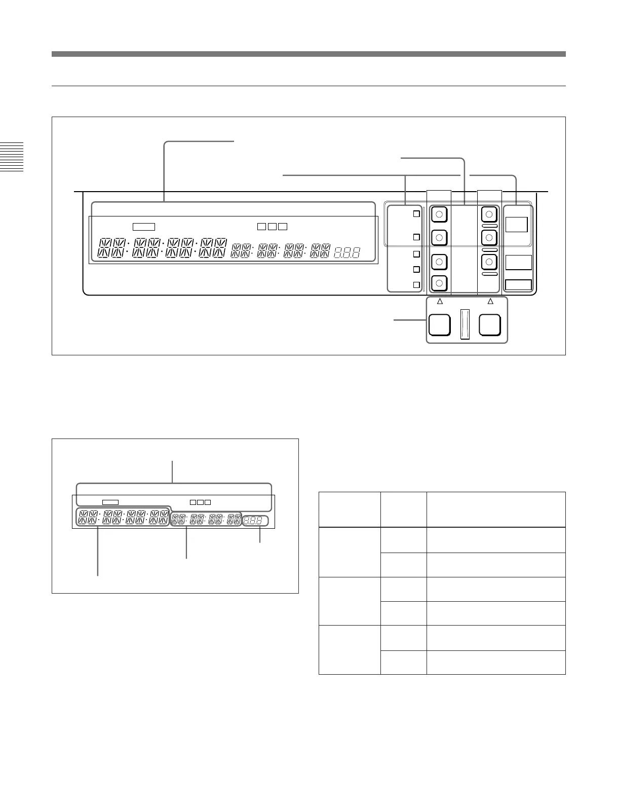
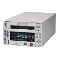
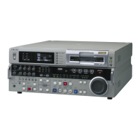
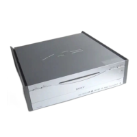
2-1 Control Panels
PLAYER RECORDER
BETACAM
SX
ALARM
DISK
BUSY
EXT
DISK
MASTER
DISK
SERVO
REC
INHIBIT
KEY
INHIBIT
FULL
EDIT
SIMPLE
EDIT
VI TC UB
INTRP A IN DF LTC VITC 8F 4F 2F
CONFI ON
CAPSTAN
LOCK
TCG TOTAL REMAIN 525 625
DOLBY
NR
EVENT
CH
CONDITION
A OUT
%
PROGRAM
TAPE
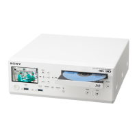
3 Device specification and display section
2 Device specification buttons and indicators
3 Indicators
1 Fluorescent display and indicators
This comprises a time data display area 1, a time data
display area 2, and an event display area provided by
the fluorescent display, and also a number of
indicators.
Time data display area 1
Normally this displays a CTL count, time code value,
or user bit value according to the setting of the CTL/
TC/UB button in the monitor/menu/display setting
section 2 and the setting of the TC switch in the
upper control panel.
It is also used to display an IN point (or audio IN
point), a duration, error messages, setup menus, and so
forth.
For details of the selection of CTL count, time code value,
or user bit value see the description of the CTL/TC/UB
button (previous page).
Indicator area
Time data display area 1
Time data display area 2
Event display area
Time data display area 2
This shows a TOTAL time indication or REMAIN
(remaining) time indication according to the setting of
the TOTAL/REMAIN button in the monitor/menu/
display setting section 2. Depending on the display,
the corresponding one of the TOTAL and REMAIN
indicators immediately above lights.
TOTAL/REMAIN indications
a) In the following description, “DISK MASTER” is also
referred to simply as “MASTER”.
b) In the following description, “DISK PROGRAM” is also
referred to simply as “PROGRAM”.
c) This is an approximate value calculated on the basis of
the detected tape diameter. It is not precise to units of
seconds.
Device
subject to
operations
DisplayTOTAL/
REMAIN
selection
1 Fluorescent display and indicators
VI TC UB
INTRP A IN DF LTC VITC 8F 4F 2F
CONFI ON
CAPSTAN
LOCK
TCG TOTAL REMAIN 525 625
DOLBY
NR
EVENT
CH
CONDITION
A OUT
%
DISK
MASTER
a)
Total number of frames recorded
on disk.
Number of frames of remaining
unrecorded capacity of disk.
DISK
PROGRAM
b)
TOTAL
REMAIN
TOTAL
Total length (frames) of program
created by editing.
Remaining length (frames) of
program during playback.
REMAIN
4 PLAYER button and RECORDER button
TAPE TOTAL Time value representing the total
tape length.
C)
REMAIN Time value representing the
remaining tape length.
C)