7-11
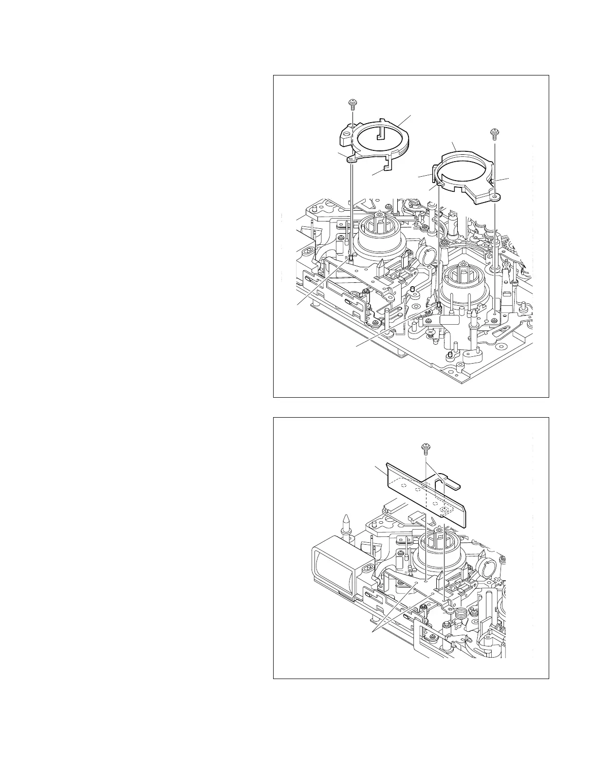
DSR-2000A/2000AP
P1.4 x 3.5
L push plate
Protrusion
P1.4 x 3
P1.4 x 3
Claw
Claw
Pin
Pin
Reference
hole
Reference
hole
Claw
Claw
Reel cover S
Reel cover T
8. Reattaching the reel cover
(1) Align the reference hole in the reel cover
with the pin in the reel motor, and hook the
two claws.
(2) Fix the reel cover S or T with the screw.
After fixing, apply screw locking compound.
Tightening Torque : 0.1 N.m {1 kgf.cm}
9. Reattaching the MIC assembly (only
when replacing the T-side brake
assembly)
Reattach the MIC assembly.
(Refer to Section 7-19.)
10. Reattaching the L push plate (only
when replacing the T-side brake
assembly)
Reattach the L-push plate with the two screws
with the two holes in the L push plate aligned
with the two protrusions on the RLR assembly.
Tightening Torque : 0.1 N.m {1 kgf.cm}
11. Reattaching the MD cover
Reattach the MD cover. (Refer to Section 7-2.)