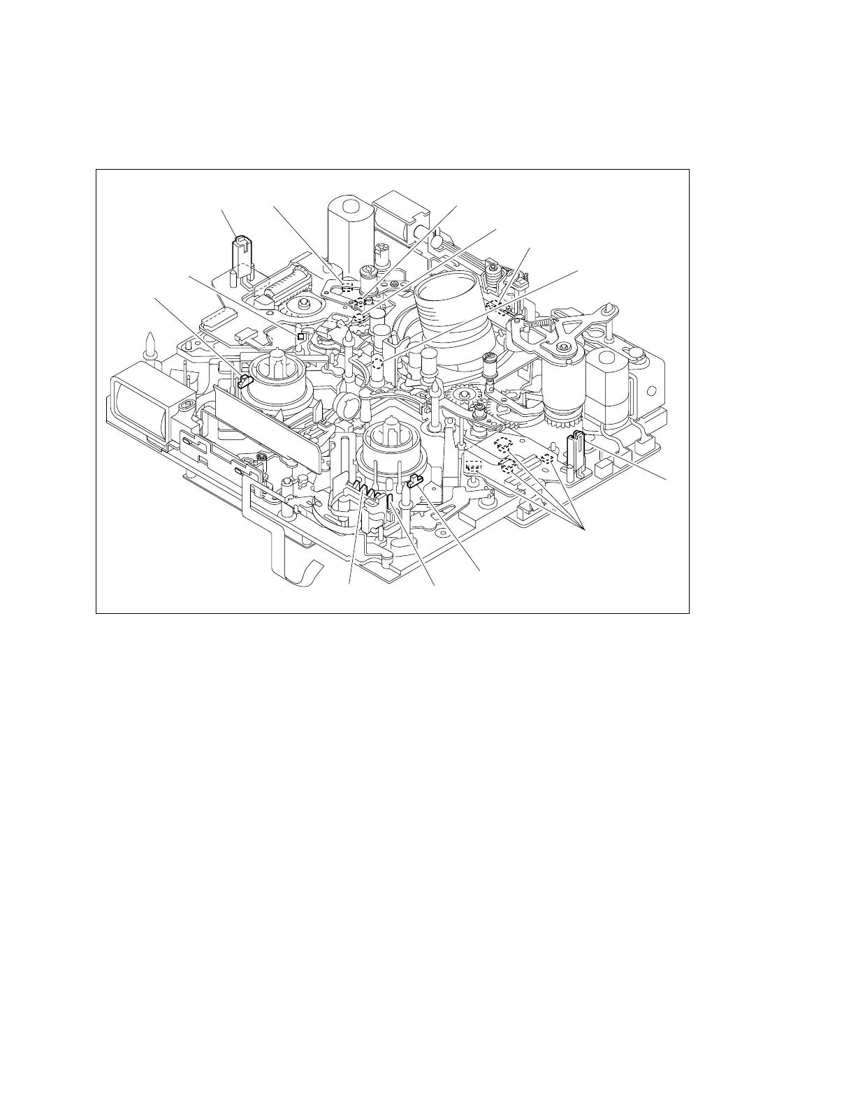
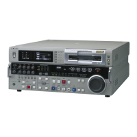
EasyManua.ls Logo

Sony DSR-2000A - Location of Sensors

Sony DSR-2000A
234 pages
Print Icon
To Next Page IconTo Next Page
To Previous Page IconTo Previous Page
Loading...
3-5
DSR-2000A/2000AP
!=
!-
7
6
5
8
9
!/
![
1
2
4
3
3-1-3. Location of Sensors
Sensor Location Diagram (1) ..... Mechanism Deck
9 Cassette memory terminal
Determines whether cassette memory is used, and
reads and writes data to and from the cassette memory.
!/ Tension sensor
The tension arm keeps the tension of a running tape
constant during recording and playing. The tension
sensor detects the mechanical position of the tension
arm.
!- Reel FG sensor (Supply side)
Detects the rotation of the supply reel table. The PG
output of the sensor is input to the servo circuit and
controls the rotating speed and torque of the reel
motor.
!= Tape end sensor
Detects the end of a tape that runs in the FWD direc-
tion.
![ Threading motor FG sensor
Detects the rotation speed of the gearbox motor. The
FG output of the sensor is input to the servo circuit and
controls the threading speed so that excessive force is
not applied to the tape during threading.
1, 2 Mode sensor
Detects the mechanism position during threading.
3 Tape top/end detect LED
Detects the top and end of a tape.
4 Condensation sensor
Detects condensation occurred in DSR-2000A/
2000AP.
5 Tape top sensor
Detects the beginning of a tape that runs in the REV
direction.
6 Reel position sensors (4 pieces) (Mini, M, Standard
reel position)
Detects the reel table position at the each specified reel
position according to the cassette type.
7 Reel FG sensor (Take-up side)
Detects rotation of the take-up reel table. The FG
output of the sensor is sent to the servo circuit and
used to control the rotating speed and torque of the reel
motor.
8 Record proof sensor (common to standard, M and mini
size cassettes)
Protects a tape from mis-recording.

Table of Contents

Related product manuals