7-13
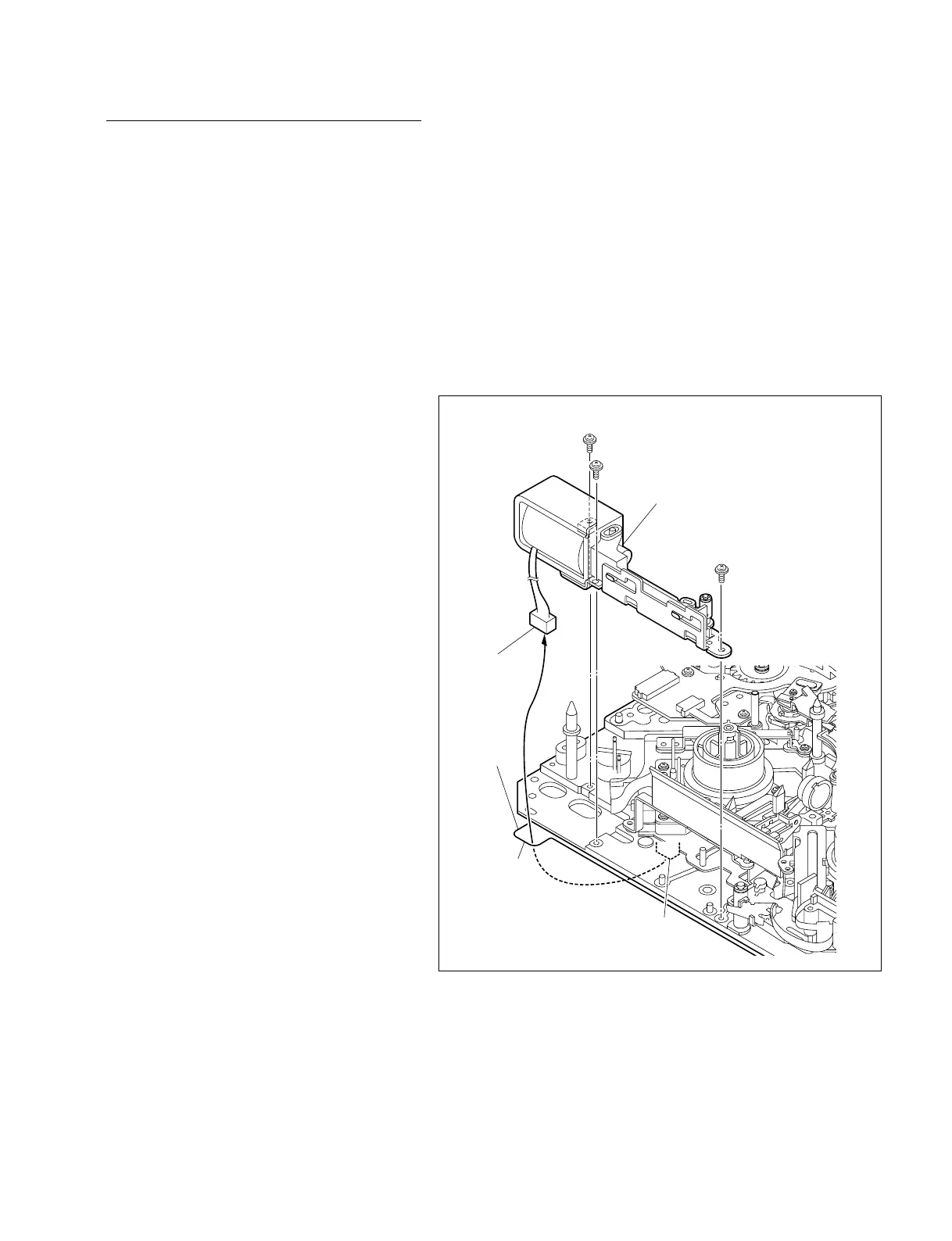
DSR-2000A/2000AP
Chassis
Harness
P1.4 x 3.5
P1.4 x 3.5
P1.4 x 3.5
Brake assembly
CN9
Hole
Replacement
1. Removing the MD cover
Remove the MD cover. (Refer to Section 7-2.)
2. Disconnecting the connector
Disconnect the harness from the connector (CN9)
on the MS-64 board located on the back side of
the MD chassis with tweezers.
n
Be careful not to suffer injury at hand by chassis
during the disconnection.
3. Removing the brake assembly
(1) Remove the three screws securing the brake
assembly.
(2) Pull out the harness of the solenoid from the
square hole in the left side of the chassis with
the brake assembly lifted up.