7-15
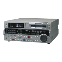
DSR-2000A/2000AP
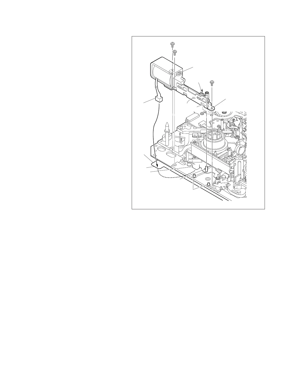
P1.4 x 3.5
Chassis
CN9
Reference pins
Harness
P1.4 x 3.5
P1.4 x 3.5
Pin of break release plate
Brake assembly
Brake base assembly
Slotted hole
Slotted hole
Hole
Hole
5. Reattaching the brake assembly
(1) Insert the harness of the brake assembly in a
square hole on the left side of the chassis to
bring it to the back side of the unit.
(2) Fit the slotted hole shown in the brake
assembly figure on the pin on the brake
release plate and further more fit the hole and
slotted hole in the brake base assembly on the
two reference pins of the MD chassis respec-
tively, and fix it with the three screws.
Tightening Torque : 0.1 N.m {1 kgf.cm}
6. Reconnecting the connector
(1) Draw out the harness of the brake solenoid to
bring it to the back side of the unit with
tweezers.
(2) Reconnect the harness to the connector
(CN9) on the MS-64 board.
7. Reattaching the MD cover
Reattach the MD cover. (Refer to Section 7-2.)
8. Checking the performance
(1) Power on the unit and press the [DEL],
[TRIM+], [MENU] keys simultaneously to
activate the maintenance menu.
(2) Following the pop-up menu in the mainte-
nance menu, enter SERVO CHECK,
PLUNGER CHECK, REEL BRAKE in order
and select REEL BRAKE.
(3) Check that the brake solenoid ON/OFF
switches smoothly by presing the
[AUDIO|IN] key and the [IN] key.