7-21
DSR-2000A/2000AP
Replacement
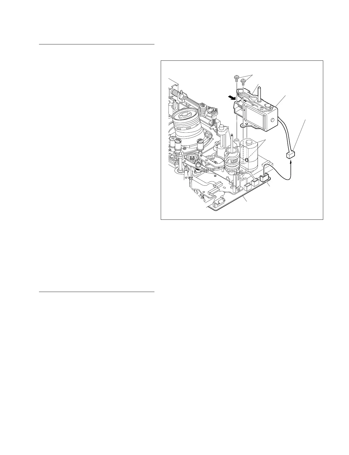
1. Removing the pinch limiter assembly
Remove the pinch limiter assembly.
(Refer to Section 7-5.)
2. Disconnecting the connectors
Disconnect the harness from the connector (CN2)
on the MS-64 board with tweezers.
3. Replacing the pinch solenoid
assembly
(1) Remove the two screws with the pinch slider
assembly drawn into the arrow direction and
lift off the pinch solenoid assembly.
(2) Align two holes in a new pinch solenoid
assembly with the two positioning pins on the
MD chassis respectively.
(3) Reattach the pinch solenoid utilizing the two
screws with the pinch slider assembly drawn
in the arrow direction.
Tightening Torque : 0.1 N.m {1 kgf.cm}
4. Reconnecting the connector
Reconnect the harness to the connector (CN2) on
the MS-64 board with tweezers.
5. Reattaching the pinch limiter
assembly
Reattach the pinch limiter assembly.
(Refer to Section 7-5.)
Adjustment after replacement
6. Checking the tape path adjustment
(Refer to Section 8-4.)
P1.4 x 3.5
Pinch solenoid assembly
Pinch slider assembly
Positioning pins
CN2
MS-64 board
Harness