7-47
DSR-2000A/2000AP
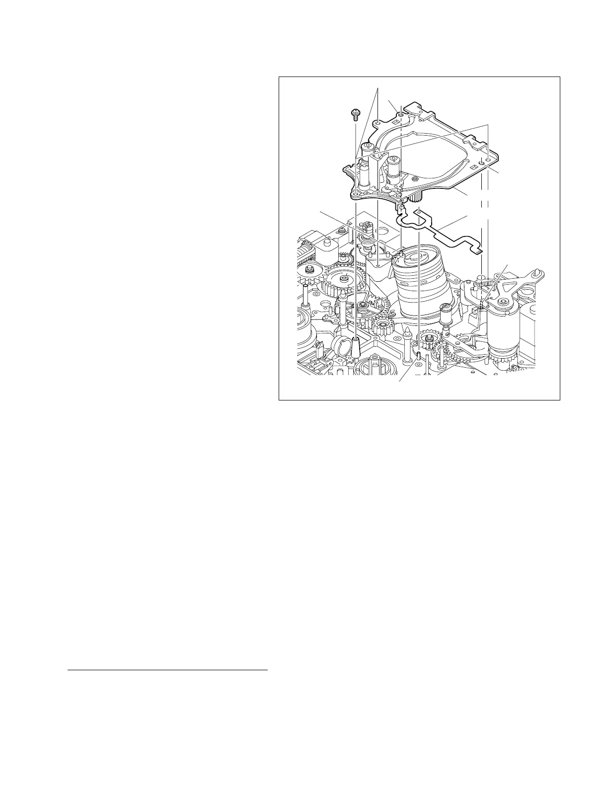
P1.4 x 3.5
Rail assembly
Slotted hole
Hole
Flexible card wire
Pin
Pin
Pin
(5) Keeping the state in step (4) and further more
holding the gear phase between S side and T
side, fit the hole and slotted hole in the rail
assembly on the two pins on the MD chassis
respectively.
(6) Fit the hole in the flexible card wire of LED
holder assembly on the pin on the MD
chassis.
(7) Fix the rail assembly with the three screws.
Tightening Torque : 0.1 N.m {1 kgf.cm}
(8) Reconnect the flexible card wire to the
connector (CN2) on the SE-522 board.
8. Reattaching the head cleaner
Reattach the head cleaner. (Refer to Section 7-21.)
9. Reattaching the RMP retainer (T1)
assembly
Fit the hole and slotted hole in the RMP retainer
(T1) assembly on the pins on the MD chassis
respectively, then fix it with the two screws.
10. Reattaching the T drawer arm
assembly
Reattach the T drawer arm assembly.
(Refer to Section 7-12.)
11. Reattaching the S tension regulator
assembly
Reattach the S tension regulator assembly.
(Refer to Section 7-11.)
12. Checking the threading/unthreading
performance
Check the threading/unthreading is performed
smoothly by turning the manual eject cover.
13. Cleaning the tape guide
Wipe the tape guides placed in followings with a
cleaning cloth moistened with cleaning fluid.
. T drawer arm assembly
. S tension regulator assembly
. Shuttle (R) assembly
. Shuttle (L) assembly
Adjustment after replacement
14. TENSION adjustment
(Refer to Section 5-3-3.)
15. Tape path adjustment
(Refer to Section 8-2.)
 Loading...