8-5
DSR-2000A/2000AP
S1
[0]
[1]
[0]
[1]
[2]
[3]
[2]
[3]
[2]
[3]
[2]
[3]
SWITCHING
H
H
L
L
H
H
L
L
H
H
L
L
S2
SW
HEAD
[2]
OFF
OFF
OFF
OFF
OFF
ON
OFF
ON
OFF
ON
OFF
ON
[5]
OFF
OFF
OFF
OFF
OFF
OFF
OFF
OFF
ON
ON
ON
ON
WJPB E1
WJPB E2
WJPB O1
WJPB O2
REC E
REC O
PRE E
PRE O
NJPB E1
NJPB E2
NJPB O1
NJPB O2
TP1
E1
TP3
TP2
E2
Tape path adjustment
board, DJ-461
0
1
2
3
4
5
6
7
8
9
A
B
C
D
E
F
ON
S2
S1
8
1
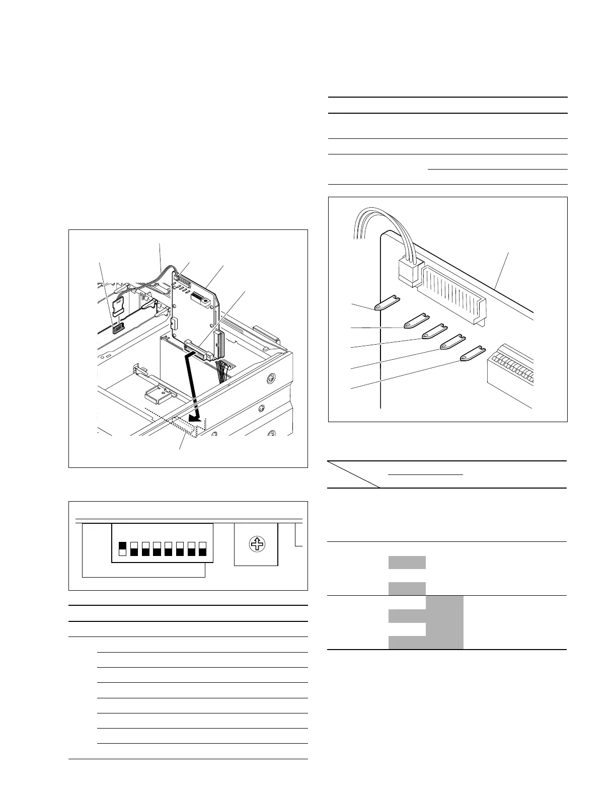
Tape path adjustment
board, DJ-461
CN1
EX-752 board (CN303)
SY-278 board
(CN113)
Harness (supplied with the board)
CN2
7. Preparation of signal measurement
Use the tape path adjustment board DJ-461 (J-6444-610-B)
to perform the tape path adjustment.
(1) Setting of the tape path adjustment board
Connect the connector CN1 on the tape path adjust-
ment board with the connector CN303 on the EX-752
board of the unit.
Connect the connector CN2 on the tape path adjust-
ment board with the connector CN113 on the SY-278
board using the harness supplied with the board.
(2) Switch setting of the tape path adjustment board
SW Bit Setting Function
S1 - 0 Select the REC head.
S2 1 OFF
2 OFF
3 OFF
4 OFF
5 OFF
6 OFF
7 OFF
8 ON Activate the switch setting of DJ-461
(3) Measuring points/signal for adjustment
Signal name Board Measuring point
RF output DJ-461 TP2
(signal after envelope detection)
Switching pulse output DJ-461 TP3
GND DJ-461 E1
DJ-461 E2
[Preference][Preference]
[Preference][Preference]
[Preference]