8-8
DSR-2000A/2000AP
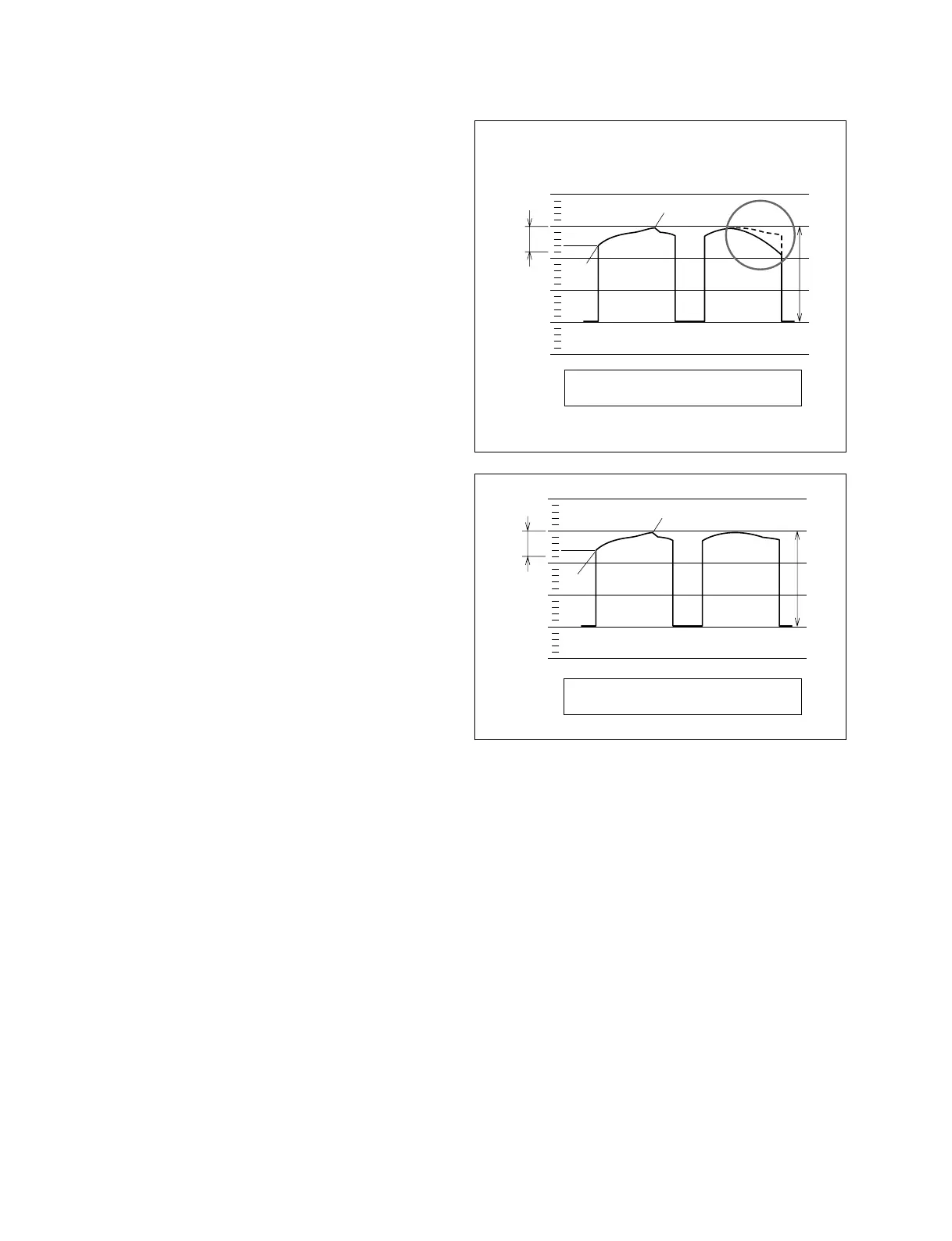
. When the RF waveform at the exit side forms the
shape of the solid line shown in Fig.4, turn the guide
T2 counterclockwise to waveform as shown by the
solid line in Fig.3. Then turn the guide T2 clockwise
to obtain the desired waveform.
n
This adjustment must end with the clockwise rotation
of the guide T2.
6. Measure the minimum amplitude of the RF waveform,
and confirm that the amplitude difference between the
maximum and the minimum of the RF waveform
satisfies the specification.
max.
3 Div
min.
4/5 Div
Fig.4
Specification : max. _ min. < 4/5 Div
3
Guide T2
Exit side
Entrance
side
4/5 Div
max.
min.
3 Div
Specification : max. _ min. < 4/5 Div