3-15
DSR-2000A/2000AP
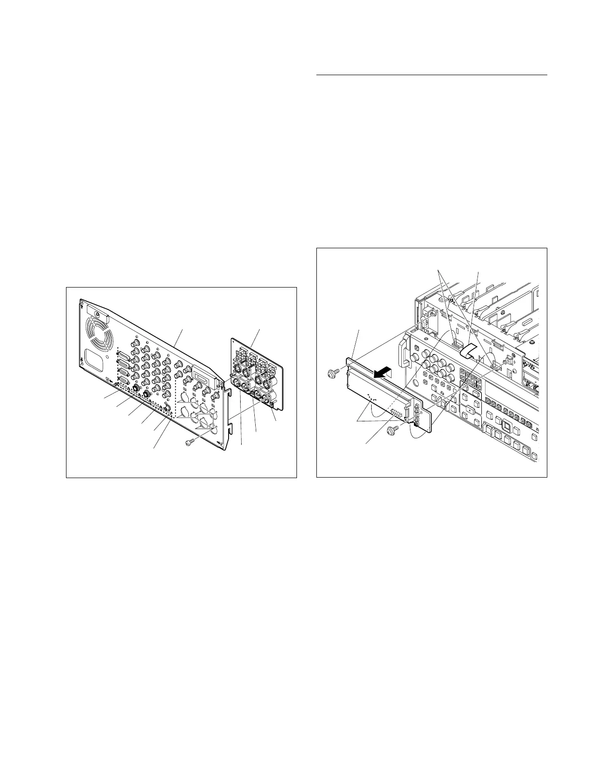
(5) Remove the eight screws while supporting the CP-342
board from the rear side, and remove the
CP-342 board.
(6) Fix temporally the CP-342 board to the rear panel with
the eight screws (BVTP3 x 10).
(7) Tighten the eight screws (BVTP3 x 10) securely and
reconnect the seven connectors disconnected in Step 2
with tweezers, using care to set the right color in the
right place.
(8) Reattach the rear panel to the unit by connecting
securely the five connectors of the CP-341 board
(CN601, CN602, CN603, CN604, and CN605) and the
three connectors of the CP-342 board (CN606, CN607,
and CN608) to the eight connectors of the MB-859
board.
(9) Fix the rear panel with the unit using the five screws.
Screws
BVTP3 x 10
CP-342 board
CP-341 board
CN608
CN607
CN606
Rear panel
CN601
CN602
CN603
CN604
CN605
Removal/Reattachment of the DY-22 board
(1) Remove the front panel. (Refer to Section 3-3.)
(2) Disconnect the flexible card wire from the connector
(CN720) of the DY-22 board,.
(3) Remove the two screws (PWH3 x 6) and remove the
DY-22 board upward.
(4) Insert the two protrusions of the DY-22 board in the
two square holes in the chassis and fix them with the
two screws.
(5) Reconnect the flexible card wire disconnected in Step
(2).
(6) Reattach the front panel.
Screw
PWH
3 x 6
DY-22 board
Protrusions
Squre holes Flexible card wire
Screw
PWH3 x 6
CN720