Do you have a question about the Sony HCD-C450 and is the answer not in the manual?
Details amplifier output power and total harmonic distortion for different modes and models.
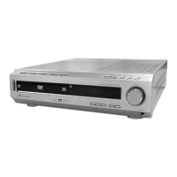
Technical specifications for Super Audio CD/DVD playback system, including laser and signal format.
Technical details for FM and AM tuners, including frequency range and antenna requirements.
Technical specs for video outputs and general operating conditions, power, dimensions.
Explains the self-diagnosis system, error codes, and corrective actions for malfunctions.
Details on optical pick-up replacement, type discrimination, and parts list.
Essential safety checks, including AC leakage measurement, after service.
Procedures for measuring AC leakage current from exposed metal parts.
Precautions for handling optical pick-up blocks and laser diode emission checks.
Guidance on checking operations with remote commanders of different models.
Lists and identifies parts and controls on the front and rear panels with page references.
Step-by-step guide for removing the top case of the unit.
Instructions for disassembling the tuner unit.
Steps for removing the front panel section of the unit.
Procedure for disassembling the power board.
Guide for disassembling the mechanism deck (CDM53K-DVBU7).
Steps for removing the RF-240 board.
Procedure for disassembling the fitting base (magnet) assembly.
Instructions for disassembling the DVD base unit (DVBU7).
Guide for disassembling the optical pick-up unit (KHM-240AAA).
Steps for disassembling the clamp motor board and assembly.
Procedure for disassembling fitting base (guide) and bracket (chassis).
Instructions for disassembling the tray component.
Steps for disassembling the chassis mold B section.
Procedure for disassembling the load motor board and assembly (M702).
Guide for disassembling the stocker section.
Steps for disassembling slider, tension spring, and shutter.
Procedure for disassembling gear assemblies (A, B, U/D Slider).
Instructions for disassembling the chucking gear.
Details on entering and using various test modes like Version, Jog, Key, Display, OSD, and Disc Tray Lock.
Comprehensive system diagnosis and general methods for checking various functions.
Procedures for drive auto-adjustment, manual operation, disc checks, and servo control.
Steps for performing electrical adjustments, particularly for the video system.
Diagram showing the location of various circuit boards within the unit.
Block diagrams illustrating the signal flow in different sections of the unit.
Printed wiring board layouts for RF, DVD, AMP, I/O, FRONT, SW, CDM, and POWER boards.
Schematic diagrams for various boards including RF, DVD, AMP, I/O, FRONT, SW, CDM, and POWER sections.
Block diagrams and pin function descriptions for key integrated circuits.
Provides exploded views of various sections like case, chassis, front panel, and mechanism.
List of electrical components for the amplifier board.
List of electrical components for the DVD board.
List of electrical components for the I/O board.
List of electrical components for the SW section.
List of electrical components for the power board.
| Type | Mini Hi-Fi Component System |
|---|---|
| Power Output | 100 W |
| CD Player | Yes |
| Radio Tuner | FM/AM |
| Bluetooth | No |
| USB Port | No |
| Remote Control | Yes |
| Speakers | 2 |
| Cassette Deck | Yes |