52
HCD-M700
Emergency code table
10. Communication error with IC001 (RF-240 board)
11. Servo lock of focus, tracking and spindle servos are lost.
12. Communication error with EEPROM and IC101 (DVD board)
13. Hours meter data write error in EEPROM, IC101 (DVD board)
14. Communication error with servo DSP, IC302 (DVD board) or
defective servo DSP
20. Tilt and sled servo initializing error. The laser unit does not
return to the initial position.
21. Tilt servo operation error
22. The move request to illegal position is issued from system control
to the tilt servo.
23. Error in the tracking balance gain adjustment.
24. The move request to illegal position is issued from system control
to the sled servo.
30. Error in the tracking balance adjustment
31. Error in the tracking gain adjustment
32. Error in the focus balance adjustment
33. Error in the focus bias adjustment
34. Error in the focus gain adjustment
35. Error in the tilt servo adjustment
36. Error in the RF equalizer adjustment
37. Error in the RF group delay adjustment
38. Amount of jitter upon completion of adaptation adjustment is
excessive.
40. Focus servo does not lock.
41. Focus jump is not possible with the dual layer (DL) disc.
50. CLV (spindle) servo does not lock.
51. Spindle does not stop.
60. The seek request to the non-existent address is issued from
system control using the DVD disc.
Version Information
Press the 5 key of the test mode to display the ROM version
information and destination data. The hexadecimal value in the
parenthesis ( ) of the version number column is the checksum value.
## Version Information ##
IF con. Ver:x. xxx (xxxx)
Group 00
SYScon. Ver:1. xxx (xxxx)
Model xx
Region xx
Servo DSP Ver:1. xxx
OPT Type : 2 Laser
Exit:RETURN
Vidoe Level Adjustment
Press the 6 key of the test mode to display the color bar signal for
video adjustment. The OSD (on-screen display) disappears while
the color bar signal is displayed. When you press any key, the display
returns to the menu screen.
Equipment required
1) Oscilloscope: single trace or dual trace, bandwidth of 100 MHz
or more, (input impedance of 10 Mohms or higher)
(1) Video level adjustment (DVD board)
<Purpose>
To align the video output signal level with the NTSC standard. If
not adjusted correctly, luminance of the video output signal may be
too bright or too dark.
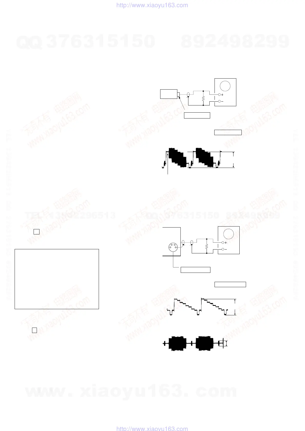
Connection
Adjustment procedure:
1) Connect an oscilloscope to the VIDEO OUT terminal.
2) Adjust the video output signal level to 1.0 ± 0.05 Vp-p.
(2) S-terminal video level check
<Purpose>
To check the S-terminal video output signal for the correct level. If
the S-terminal video output is not correct, picture will not appear
even when the monitor TV is connected to the S-terminal cable.
Connection
Adjustment procedure:
1) Connect an oscilloscope to the S-VIDEO OUT terminal.
2) Confirm that the S-Y level is 1.0 ± 0.1 Vp-p.
3) Connect an oscilloscope to the S-VIDEO OUT (S-C) terminal.
4) Confirm that the S-C burst signal level is 286 ± 80 mVp-p.
J601
VIDEO OUT terminal
75
Ω
Oscilloscope
set
1.0
±
0.05Vp-p
(White 75%)
J600
S-VIDEO OUT terminal
75
Ω
Oscilloscope
G
G
set
1.0
±
0.1Vp-p
286
±
80mVp-
w
w
w
.
x
i
a
o
y
u
1
6
3
.
c
o
m
Q
Q
3
7
6
3
1
5
1
5
0
9
9
2
8
9
4
2
9
8
T
E
L
1
3
9
4
2
2
9
6
5
1
3
9
9
2
8
9
4
2
9
8
0
5
1
5
1
3
6
7
3
Q
Q
TEL 13942296513 QQ 376315150 892498299
TEL 13942296513 QQ 376315150 892498299
http://www.xiaoyu163.com
http://www.xiaoyu163.com