443
To set to crop to 4:3 when a DME wipe is executed
When side flags are enabled, you can automatically crop
an image to be a 4:3 image when executing a DME wipe.
In the Side Flags menu (7331.7), press [Auto Crop],
turning it on.
The settings are common to the M/E and PGM/PST banks.
Adjusting the width of the side flags
1
In the Engineering Setup >Switcher >Config >Side
Flags menu (7331.7), press [Width].
2
Set the following parameters.
Enabling and disabling side flags
Press a button in the Engineering Setup >Switcher
>Config >Side Flags menu (7331.7) to display the setup
menu.
To enable/disable side flags in the menu
Press [Misc >Enable >Side Flags] to open the Misc
>Enable >Side Flags menu (3213) and configure the
settings (see page 197).
To assign side flag operation buttons to cross-
point buttons
Press [Side Flags Button Assign] to open the Engineering
Setup >Panel >Xpt Assign >Side Flags Button Assign
menu (7322.10) and configure the settings (see page 417).
Setting the Sub Key Mode
When using the XKS-8210/XKS-7210 Mix Effect Boards,
key 3 and key 4 function as sub keys when the switcher
signal format is 3840×2160P.
Key 4 cannot be used when key preview is enabled for key
3.
1
In the Engineering Setup >Switcher >Config menu
(7331), press [Key Config].
The Key Config menu (7331.9) appears.
2
In the status area, select the target switcher bank to set.
3
In the <Sub Key Mode> group, select the sub key
mode.
Key3, Key4: Use key 3 and key 4 as sub keys (key
preview is disabled).
Key3 + Key PVW: Use only key 3 as a sub key (key
preview is enabled).
Setting the Keys and DME Channels
used in a CG Border
You can set the keys and DME channels used when
changing the position and size of the image embedded in
the CG border.
1
In the Engineering Setup >Switcher >Config menu
(7331), press [CG Border Int Video Ch Assign].
The CG Border Int Video Channel Assign menu
(7331.15) appears.
2
In the status area, select the target switcher bank to set.
3
In the <Key1 CG Border Enable> to <Key8 CG
Border Enable> groups, select the DME channels.
Ch1-2: Set DME channels 1 and 2 for the CG border
with the target key (Key1 to Key8).
Ch3-4: Set DME channels 3 and 4 for the CG border
with the target key (Key1 to Key8).
[Ch1-2] cannot be selected if DME channel 1 or 2 is
assigned to the target key. Similarly, [Ch3-4] cannot
be selected if DME channel 3 or 4 is assigned to the
target key.
Setting Extended Re-Entry
When extended re-entry is enabled, the restrictions
relating to re-entry signal selection are removed.
The following two types of extended re-entry can be
configured.
• Extended re-entry for switcher banks
Re-entry signals can be selected within the same
switcher bank.
• Extended re-entry for keyers
Re-entry signals can be selected using key bus/utility
1 bus (regardless of constraints, such as M/E
configuration) when the switcher signal format is
3840×2160P or 1080P.
• The extended re-entry settings are common to all
switcher banks.
• Extended re-entry for keyers is available only when the
switcher signal format is 3840×2160P or 1080P.
• A delay may occur in the re-entry signal when extended
re-entry is enabled.
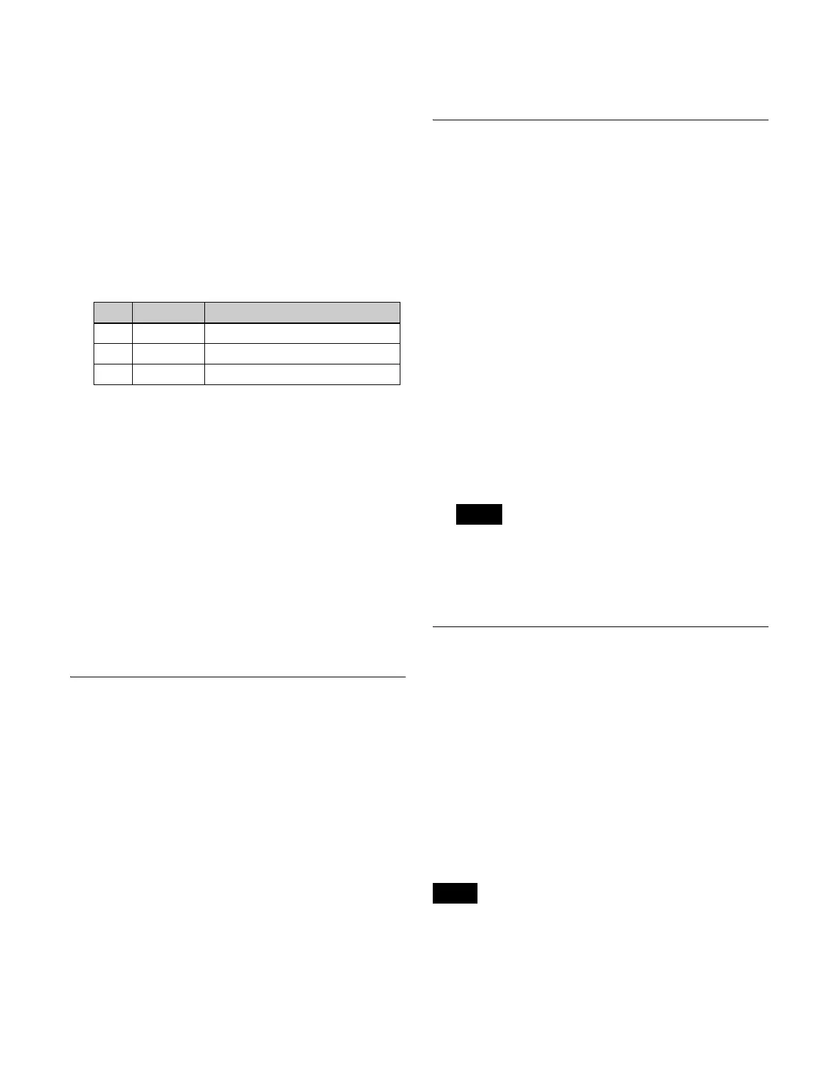
No. Parameter Adjustment
3 Left Width of left side flag
4 Right Width of right side flag
5 All Width of left and right side flags
Note
Notes

 Loading...


