76
Overview
The cross-point control block and AUX bus control block
each have 36 cross-point buttons.
These buttons are identified by numbers common to all of
the banks and the control block, and a signal is assigned to
each number.
The basic signal selection process is to select, in a cross-
point button row, the cross-point button to which is
assigned the desired signal.
Re-entry buttons
Re-entry buttons are assigned to the cross-point button
rows in the cross-point control block and AUX bus control
block (AUX bus operation mode).
Re-entry buttons are used to load an image created on a
switcher bank (M/E and PGM/PST) as an input signal on
another switcher bank.
For example, to load the output image from the M/E-1
bank as the background B on the M/E-2 bank, press the
M/E-1 re-entry button in the cross-point button row for
background B bus in the cross-point control block of the
M/E-2 bank.
• In 36-button rows, the M/E-1 to M/E-3 and PGM/PST
re-entry buttons are assigned to buttons numbered 32 to
35.
The M/E-4 and M/E-5 re-entry buttons must be assigned
in the Setup menu (see page 414).
• Re-entry buttons can also be assigned to the cross-point
pad (see page 434).
• When extended re-entry is enabled for switcher banks,
re-entry signals within the same switcher bank can be
selected.
Re-entry signal restrictions
Up to four re-entry stages are supported.
The following restrictions apply, depending on the signal
format and M/E configuration, for re-entry signal
selection.
a) When extended re-entry for keyers is enabled, re-entry signals can be
selected on the key bus and utility 1 bus.
b) When using an XKS-8215 Mix Effect Board on the XVS-9000, re-entry
signals cannot be selected on a key bus or the utility 1 bus.
c) For example, if M/E-1 is selected on the M/E-2 background A bus (or
background B bus, key bus, utility 1 bus, or utility 2 bus), then M/E-1 and
M/E-2 cannot be selected on the M/E-3 key bus or utility 1 bus.
Extended re-entry
The following re-entry signal selections are available
when extended re-entry is enabled in the Setup menu.
• Re-entry signal selection within the same switcher bank
(extended re-entry for switcher banks).
• Re-entry signal selection using key bus/utility 1 bus on
3M/E or higher configurations when the switcher signal
format is 3840×2160P or 1080P (extended re-entry for
keyers).
For details, see “Setting Extended Re-Entry” (page 443).
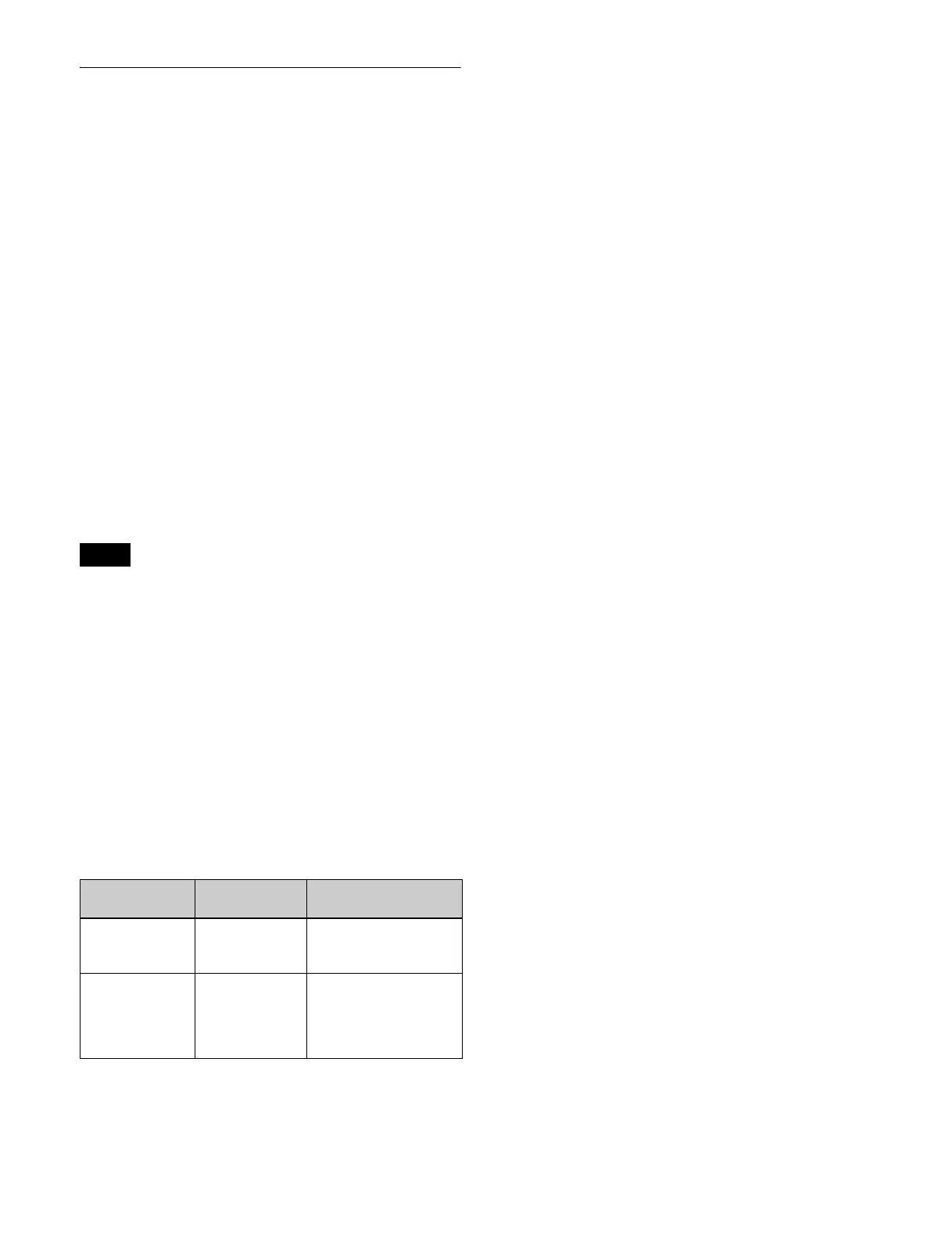
Notes
Signal format M/E
configuration
Restrictions
• 1080P
• 3840×2160P
3M/E to 6M/E Re-entry signals not
selectable on a key bus
or the utility 1 bus.
a)
• 720P 4M/E to 6M/E Re-entry signals
spanning more than
two stages not
selectable on a key bus
or the utility 1 bus.
b) c)

 Loading...


