64
POWER A, B, C, D, E, F switch and status indicators
(XVS-9000)
POWER A, B, C, D switch and status indicators
(XVS-8000/7000)
POWER A, B switch and status indicators (XVS-6000)
Turn the POWER switch on/off to power the unit on/off.
The unit is turned on when the POWER switch is in the “?”
position, and turned off when in the “1” position.
The status indicators and power supply status are given
below.
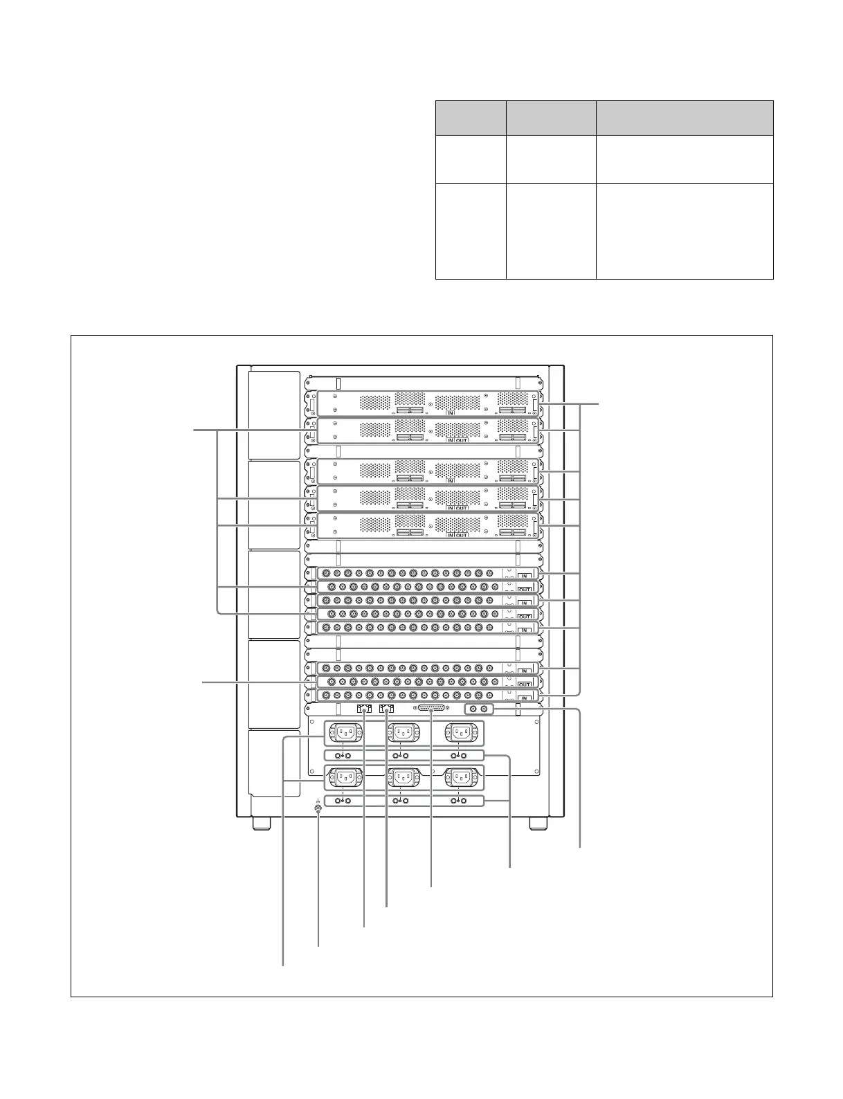
Rear view
Indicator
status
AC status
indicator
DC status indicator
Lit green AC input within
specified
range
POWER switch on, and AC
input and DC output within
specified range
Off AC input
outside
specified
range
Indicates one of the following.
•POWER switch off
• AC input outside specified
range
• DC output outside specified
range
q UTL LAN connector
c MV OUTPUT 1 to
16 connectors
r GPI connector
t REF IN connectors
s RESET CIRCUIT BREAKER buttons
XVS-9000
a INPUT 1 to 160 connectors
b OUTPUT 1 to
80 connectors
n - AC IN A, B, C, D, E, and F connectors
o U terminal
p MVS LAN connector

 Loading...


