68
About 4K signal input/output connector
assignment (SDI connector boards)
In 4K format, a subdivided-by-4 image (sub images) are
transferred as four separate signals, where the 4K signal is
assigned to four input/output connectors.
On connector boards that support 12G-SDI,
1)
a 4K signal
can be transferred using a single cable.
1) 12G-SDI is an interface for digital transfer of 4K signals using a co-axial
cable that supports 12 Gbps transfer speeds.
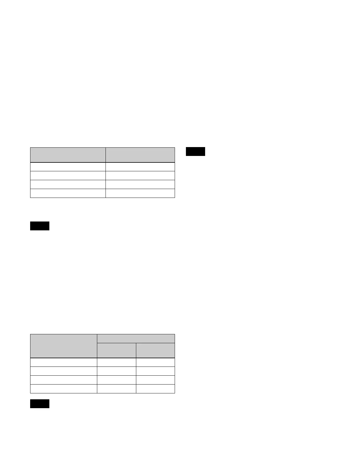
When assigning to four connectors
On the following connector boards, a 4K signal is assigned
to a group of four connectors.
• Input connector boards: XKS-S8110/XKS-S8111
• Output connector boards: XKS-S8165
The assignment is as follows.
a) The connector numbers correspond to sub images 1, 2, 3, and 4 in that
order.
On connector boards that support 12G-SDI (XKS-S8112/
XKS-S9112/XKS-S8167/XKS-S9167), four signals are
transferred in the following cases.
• For input/output of 3840×2160P 2SI 3G, 3840×2160P
SQD, and 3840×2160PsF SQD signals
• When the XKS-S8167 output connectors are set to 3G
mode
When assigning to one connector (12G-SDI)
On the following connector boards, a 4K signal
(3840×2160P 2SI 12G) is assigned to a single connector.
• Input connector boards: XKS-S8112/XKS-S9112
• Output connector boards: XKS-S8167/XKS-S9167
The assignment is as follows.
• The XKS-S8112/XKS-S8167 use the input connectors/
output connectors with the first number (1, 5, 9, and so
on) of each group of four connectors.
• The XKS-S9112/XKS-S9167 use the input connectors/
output connectors with odd numbers (1, 3, 5, and so on).
About output connectors of 12G-SDI
connector boards
The output connectors of the XKS-S8167/XKS-S9167
12G-SDI Output Boards can be enabled/disabled.
When disabled, no signal is output from the output
connector.
If a cable is not connected to an enabled output connector,
radio wave interference may occur. Disable unused output
connectors.
For details, see “Enabling/Disabling SDI Output
Connectors” (page 405).
On the XVS-9000, when the switcher signal format is
3840×2160P 2SI, if the signal format of the odd-numbered
output connectors on the XKS-S9167 is set to 3840×2160P
2SI 12G, a signal converted to 1080i format is output on
the subsequent even-numbered output connectors.
About network connector boards
The XKS-C8111/XKS-C9111/XKS-C9111N/
XKS-C9121/XKS-C9121N/XKS-C8166 have the
following restrictions.
• Two slots per board are required for the installation of
XKS-C9111/XKS-C9111N/XKS-C9121/
XKS-C9121N.
• The XKS-C9111/XKS-C9121 and XKS-C9111N/
XKS-C9121N cannot be installed at the same time.
• The XKS-C9121/XKS-C9121N supports both inputs
and outputs (bidirectional).
• On the XKS-C9111N/XKS-C9121N, input/outputs 7
and 15 on each board cannot be used.
The XKS-C9111N/XKS-C9121N support 3840×2160P
2SI signal format. Accordingly, odd-numbered input/
outputs can be configured, but input/outputs that are
multiples of 8 minus 1 (7, 15, 23, and so on) are invalid.
• The XKS-C8111/XKS-C8166 cannot be installed at the
same time as the XKS-T8110/XKS-T8165.
4K format input signal/
output signal
Connector number
a)
1st system 1, 2, 3, 4
2nd system 5, 6, 7, 8
3rd system 9, 10, 11, 12
(and so on) (and so on)
Note
4K format input signal/
output signal
Connector number
XKS-S8112/
XKS-S8167
XKS-S9112/
XKS-S9167
1st system 1 1
2nd system 5 3
3rd system 9 5
(and so on) (and so on) (and so on)
Notes
Note

 Loading...


