- 27 -
V SIZE
V LIN
AFC BOW
V POSITION
H POSITION
H SIZE
PIN AMP
PIN PHASE
UP-CPIN
AFC ANGLE
LO-CPIN
1. Program the Remote Commander for operation in Service Mode.
[ See Page 24 ] and enter into ‘Service Mode’ by pressing
‘VIDEO’ button twice. Enter into the ‘Device Register Setting’
then ‘Deflection’ service menu.
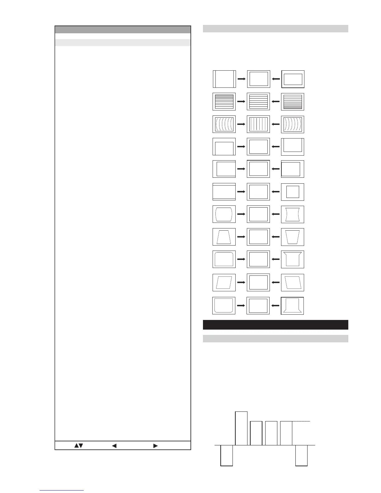
2. Select and adjust each item in order to obtain the optimum image.
Deflection System Adjustment
Same Level
B-Out Waveform
4-2. Volume Electrical Adjustments
Sub Colour Adjustment
1. Input a PAL colour bar signal.
2. Connect an oscilloscope to CN5400 pin 5 located on the C
Board.
3. Program the Remote Commander for operation in Service Mode.
[ See Page 24 ] and enter into ‘Service Mode’ by pressing
‘VIDEO’ button twice. Enter into the ‘Device Register Setting’
then ‘Backend’ service menu.
4. Adjust ‘Sub Colour’ data so that the right sides of the waveform
are of equal height.
noitcelfeD
oN rcseD feD niM xaM ataD
1eziS-H1303683
2noitisoP-H2203651
3eziS-V0203671
4noitisoP-V1303672
5pmA-niP1303692
6nipC-pU1303672
7nipC-oL1303693
8woB-CFA703604
9elgnA-CFA703652
01esahP-niP1303632
11niL-V70517
21rroC-S70515
311-noitatoR1030
412-noitatoR510517
51parT-H10138
61raeniLH58055258
71pmA-raP-CH003673
81pmA-raP-PM30517
91sixAniPpU3032
02sixAniPoL3032
12niaGniPpU3030
22niaGniPoL3030
32miT-BKA5101351
42ffO-KLBFFOFFONOFFO
52ffO-BKAFFOFFONOFFO
62klB-pU00510
72klB-oL00510
82nO-VNOFFONONO
92cD-wEFFOFFONOFFO
03loP-cUFFOFFONOFFO
13wS-klbVFFOFFONOFFO
23esahP-cnyS0030
33edoM-CFA2032
43wS-tsRFFOFFONOFFO
53klB-tfeL2503625
63esahP-plC3033
73klB-thgiR80368
83etaG-plCFFOFFONOFFO
93wS-klbHFFOFFONOFFO
04tcepsA-V00360
14wS-mooZFFOFFONOFFO
24wS-pmJFFOFFONOFFO
34llorcS-V1303613
44qerF-V2032
54nilV-pU00510
64nilV-oL00510
74pmoC-V00519
84pmoC-H00510
94cD-1waSV70517
05pmoC-niP0070
15pmA-1waSV80130
25pmoC-CFA2032
35cD-raP-PM20512
45cD-raP-CH1303613
55wS-psAFFOFFONOFFO
65wS-vrDVFFOFFONOFFO
75ahP-raP-CH1303613
:metIretnE:unemtsaL:tceleS