par une marque sont dune importance
critique pour la sécurité. Ne les remplacer
que par des pièces de numéro spécifié.
specified.
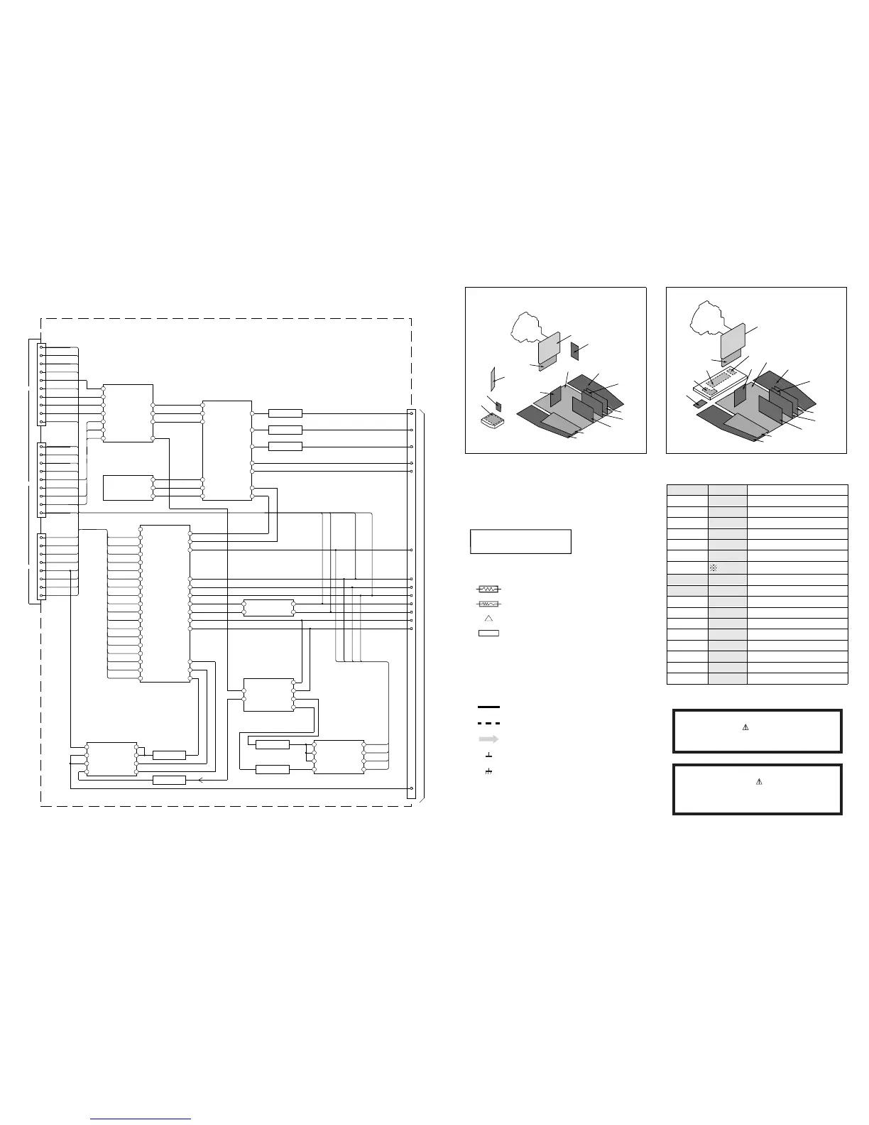
5-2. CIRCUIT BOARD LOCATION
5-3. SCHEMATIC DIAGRAMS AND
PRINTED WIRING BOARDS
Note :
• All capacitors are in µF unless otherwise noted.
• pF : µµF 50WV or less are not indicated except for
electrolytic types.
• Indication of resistance, which does not have one for
rating electrical power, is as follows.
Pitch : 5mm
Electrical power rating : 1/4W
• Chip resistors are 1/10W
• All resistors are in ohms.
k = 1000 ohms, M = 1000,000 ohms
• : nonflammable resistor.
• : fusible resistor.
• : internal component.
• : panel designation or adjustment for repair.
• All variable and adjustable resistors have
characteristic curve B, unless otherwise noted.
• All voltages are in Volts.
• Readings are taken with a 10Mohm digital mutimeter.
• Readings are taken with a color bar input signal.
• Voltage variations may be noted due to normal production
tolerences.
• : B - bus.
• : RF signal path.
• : earth - ground.
• : earth - chassis.
Reference Information
RESISTOR RN : METAL FILM
RC : SOLID
FPRD : NON FLAMMABLE CARBON
FUSE : NON FLAMMABLE FUSIBLE
RS : NON FLAMMABLE METAL OXIDE
RB : NON FLAMMABLE CEMENT
RW : NON FLAMMABLE WIREWOUND
: ADJUSTMENT RESISTOR
COIL LF-8L : MICRO INDUCTOR
CAPACITOR TA : TANTALUM
PS : STYROL
PP : POLYPROPYLENE
PT : MYLAR
MPS : METALIZED POLYESTER
MPP : METALIZED POLYPROPYLENE
ALB : BIPOLAR
ALT : HIGH TEMPERATURE
ALR : HIGH RIPPLE
Les composants identifiés par une trame et
Note :
The components identified by shading
and marked are critical for safety.
Replace only with the part numbers
specified in the parts list.
Note :
• : B + bus.