D:\Chin Meng's job\SONY-LCD\SY0142_Z115 (Rev-2)\3293042121_GB\01GB01BAS_GB.fm
4 (GB)
KLV-26S400A/3-293-042-12(1)
GB
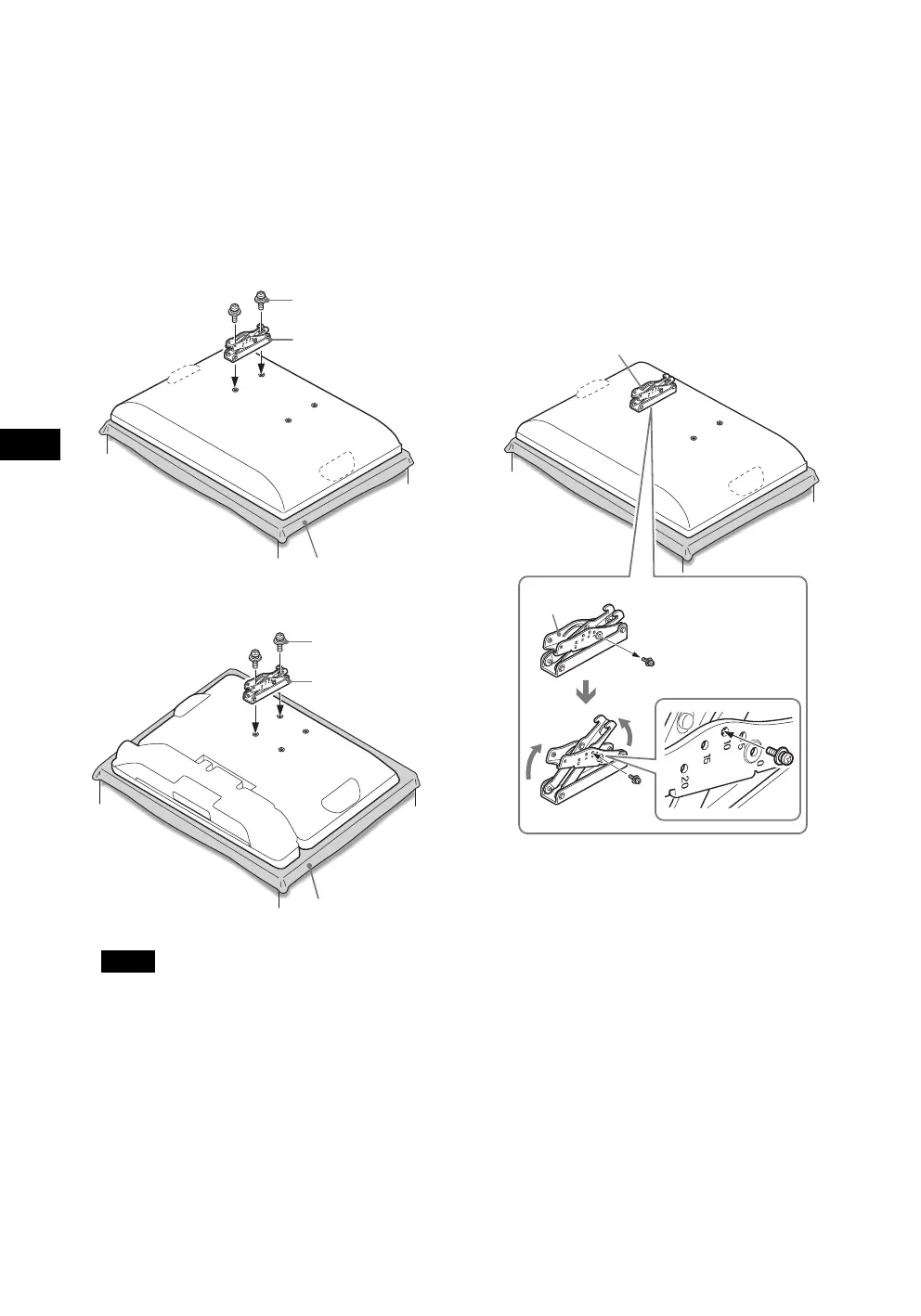
2 Secure the Mounting Hook from the left side
of the rear of the TV.
1 Secure the Mounting Hook to the rear of the TV
temporarily, using the supplied two screws (+PSW4 ×
12).
2 Be sure that both screws are tightened securely with
equal torque strength to the rear of the TV.
B For KLV-26S400A/KLV-26T400A/KLV-26T400G/
KLV-19T400A/KLV-19T400G
B For KLV-19T400W
Notes
• If you install the right Mounting Hook first, it will be
difficult to adjust its angle. Install the left Mounting
Hook first.
• Be sure not to use any screws other than the supplied
ones (+PSW4 × 12) when securing the Mounting
Hook.
3 Adjust the angle of the Mounting Hook.
When installing the TV parallel to the wall (0 degrees),
adjustment of the Mounting Hook angle (procedures
1 and 2 below) is not necessary.
1 Remove the angle adjusting screw from the arm of the
Mounting Hook. Choose the holes corresponding to
the desired angle (5, 10, 15 or 20 degrees).
2 Firmly secure the arm using the screw removed in the
previous procedure 1.
B For KLV-26S400A/KLV-26T400A/KLV-26T400G/
KLV-19T400A/KLV-19T400G
Screw
(+PSW4 × 12)
Soft cloth
Mounting Hook
Screw
(+PSW4 × 12)
Soft cloth
Mounting Hook
Mounting Hook
Arm
1
2
Arm
KLV26S400A_GB.book Page 4 Tuesday, June 24, 2008 9:14 AM