— 28 —
KP-43T85T / 53SV85T / 61SV85T
4-1.TV INPUT SUB CONTRAST ADJUSTMENT
(VPNT-SCON)
1. Display a color bar signal through the TV’s VHF/UHF input.
2. Mode: Personal 1 or 2
PICTURE:............... maximum COLOR:...................... minimum
BRIGHTNESS: ............. center COLORTEMP:................neutral
3. Enter the service mode.
4. Turn off the blue and red CRTs by changing the data from “1” to
“0” in category VPNT item 28 RON (red), and item 30 BON (blue).
If this step is not followed, the ABL circuit may prevent you from
adjusting the peak-to-peak amplitude to 1.8 V.
5. Connect an oscilloscope between pin 7 of CN204 (A board) and
ground.
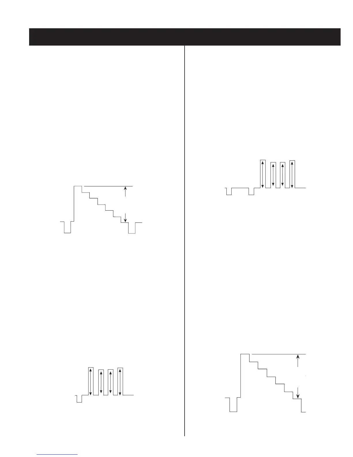
6. Select adjustment category “VPNT” adjustment item 19 “SCON”,
and adjust using the 3 or 6 button on the remote so that the wave
form level is 1.80 ± 0.05Vp-p.
1.80 ± 0.05 Vp-p
White
Black
7. Press “MUTING” and then “ENTER” to save the adjustment data.
4-2.VIDEO INPUT SUB-HUE AND SUB-COLOR
ADJUSTMENT (VPNT-SHUE, SCOL)
1. Display a color bar signal through a video input.
2. Mode: Personal 1 or 2
PICTURE:............... maximum COLOR:...........................center
BRIGHTNESS: ............. center COLORTEMP:................neutral
3. Enter the service mode.
4. Connect an oscilloscope between pin 5 of CN204 (A board) and
ground.
5. Alternately select adjustment category “VPNT” adjustment item #20
“SHUE” and item #21 “SCOL”, and adjust them so that VB1 = VB4,
and VB2 = VB3 as shown below.
VB1
VB2 VB3
VB4
6. Add 2 to the adjusted value of “SCOL”.
7. Press “MUTING” and then “ENTER” to save the adjustment data.
4-3.COMPONENT INPUT SUB-HUE AND SUB-
COLOR ADJUSTMENT (DAC-UVSH, UVSC)
1. Select VIDEO 4 and display a color bar signal.
2. Mode: Personal 1 or 2
PICTURE:............... maximum COLOR:...........................center
BRIGHTNESS: ............. center COLORTEMP:................neutral
3. Enter the service mode.
4. Connect an oscilloscope between pin 5 of CN204 (A board) and
ground.
5. Alternately select adjustment category “DAC”, adjustment item # 0
“UVSH” and item #1 “UVSC” and adjust them so that VB1 = VB4 and
VB2 = VB3 as shown below.
VB1
VB2 VB3
VB4
6. Press “MUTING” and then “ENTER” to save the adjustment data.
4-4.PIP SUB CONTRAST ADJUSTMENT
(PYC-PSCN)
1. Display a color bar signal through the TV’s VHF/UHF input.
2. Mode: Personal 1 or 2
PICTURE:............... maximum COLOR:...................... minimum
BRIGHTNESS: ............. center COLORTEMP:................neutral
3. Enter the service mode, and then select the PIP (Picture-in-Picture)
mode.
4. Select an unused video input for the main picture (it must be black),
and select the tuner for the small picture (it must be showing
colorbars).
5. Connect an oscilloscope between pin 7 of CN204 (A board) and
ground.
6. Select adjustment category “PYC”, adjustment item # 0 “PSCN” and
adjust so that the peak-to-peak voltage is 1.65 ± 0.05Vp-p as shown
below.
1.65 ± 0.0
White
Black
7. Press “MUTING” and then “ENTER” to save the adjustment data.
SECTION 4: CIRCUIT ADJUSTMENTS
 Loading...