— 3 —
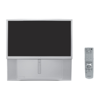
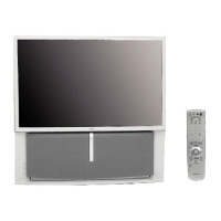
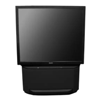
KP-43T85T / 53SV85T / 61SV85T
TABLE OF CONTENTS
Specifi cations........................................................................ 4
Warnings and Cautions......................................................... 5
Safety Check-out .................................................................. 6
Self-Diagnostic Function....................................................... 7
1. Disassembly
1-1. Rear Board Removal .......................................................... 10
1-2. Chassis Assembly Removal ............................................... 10
1-3. Service Position .................................................................. 10
1-4. HA and HB Board Removal (All Except KP-43T85T) ......... 11
1-5. HA and HB Board Removal (KP-43T85T only)................... 11
1-6. Beznet Assembly Removal ................................................. 11
1-7. Mirror Cover Removal ......................................................... 12
1-8. HC Board and S Board Remvoal........................................ 12
1-9. A and G Board Removal ..................................................... 12
1-10. HV Cable Installation and Removal .................................... 13
1-11. Picture Tube Removal ......................................................... 13
2. Set-up Adjustments
2-1. Screen Voltage Adjustment................................................. 14
2-2. Screen (G2) Adjustment ..................................................... 14
2-3. Defl ection Yoke Tilt Adjustment........................................... 14
2-4. Focus Lens Adjustment ...................................................... 14
2-5. Focus Control Adjustment................................................... 15
2-6. 2-Pole Magnet Adjustment.................................................. 15
2-7. 4-Pole Magnet Adjustment.................................................. 16
2-8. Defocus Adjustment............................................................ 16
2-9. Electrical Adjustments By Remote Commander................. 16
2-10. Registration Adjustment (PJE mode only) .......................... 22
2-11. Green Registration Adjustment........................................... 23
2-12. Red Registration Adjustment .............................................. 24
2-13. Blue Registration Adjustment.............................................. 24
2-14. Auto Registration Adjustment ............................................. 25
3. Safety Related Adjustments (G Board)
3-1. HV Regulation Circuit Check and Adjustment .................... 26
3-2. HV Hold Down Circuit Operation Check and Adjustment ... 26
3-3. +B Max Voltage Confi rmation ............................................. 27
3-4. +B OVP Confi rmation ......................................................... 27
4. Circuit Adjustments
4-1. TV Input Sub Contrast Adjustment ..................................... 28
4-2. Video Input Sub-Hue and Sub Color Adjustment ............... 28
4-3. Component Input Sub-Hue and Sub-Color Adjustment...... 28
4-4. PIP Sub-Contrast Adjustment ............................................. 28
4-5. PIP Sub-Hue, Sub-Color Adjustment.................................. 29
4-6. User Control Bar Graph Display Position Adjustment......... 29
4-7. PIP Position Adjustment ..................................................... 29
5. Diagrams
5-1. Circuit Boards Location....................................................... 30
5-2. PWB and Schematic Diagrams Information........................ 30
5-3. Block Diagrams................................................................... 32
5-4. Frame Schematic Diagram ................................................. 40
Schematics and Supporting Information
A Board............................................................................... 41
CB Board ............................................................................ 46
CG Board............................................................................ 47
CR Board ............................................................................ 48
FA Board ............................................................................. 49
FB Board............................................................................. 49
G Board .............................................................................. 51
HA Board ............................................................................ 53
HB Board ............................................................................ 54
HC Board ............................................................................ 55
S Board............................................................................... 55
5-5. Semiconductors .................................................................. 56
6. Exploded Views
6-1. Cover (KP-43T85T)............................................................. 58
6-2. Chassis (KP-43T85T) ......................................................... 59
6-3. Picture Tube (KP-43T85T) .................................................. 60
6-4. Cover (KP-53SV85T) .......................................................... 61
6-5. Chassis (KP-53SV85T)....................................................... 62
6-6. Picture Tube (KP-53SV85T)................................................ 63
6-7. Cover (KP-61SV85T) .......................................................... 64
6-8. Chassis (KP-61SV85T)....................................................... 65
6-9. Picture Tube (KP-61SV85T)................................................ 66
7. Electrical Parts List ......................................................................... 67
SECTION TITLE PAGE SECTION TITLE PAGE
 Loading...