28
RCD-W10
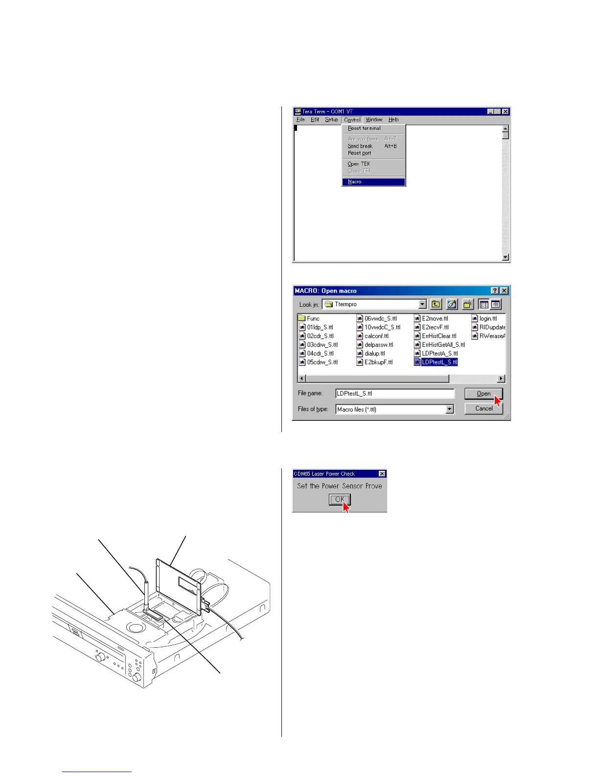
1) Select the menu as follows. Control → Macro, and select
LDPtestL_S.ttl.
Press “Open”. (Fig. 3-1, 3-2)
4 Fig. 3-1
4 Fig. 3-2
4 Fig. 3-3
3) Place probe of a laser power meter in the specified position
following the display as shown in Fig. 3-3. (See Fig. 3-3-a)
jig
CDM65-RBD1
optical pick-up
sensor probe
4 Fig. 3-3-a
3. Locating the Faulty Point
3-1. Laser Power Check
2) Press the “RESET” button (SW101) of the jig as prompted by the display.
Note : Do not add stress to an optical pick-up.
 Loading...