21
RCD-W10
SECTION 5
ELECTRICAL ADJUSTMENTS
Note :
1. CD Block is basically designed to operate without adjustment.
Therefore, check each item in order given.
2. Use YEDS-18 disc (3-702-101-01) unless otherwise indicated.
3. Use an oscilloscope with more than 10MΩ impedance.
4. Clean the object lens by an applicator with neutral detergent
when the signal level is low than specified value with the
following checks.
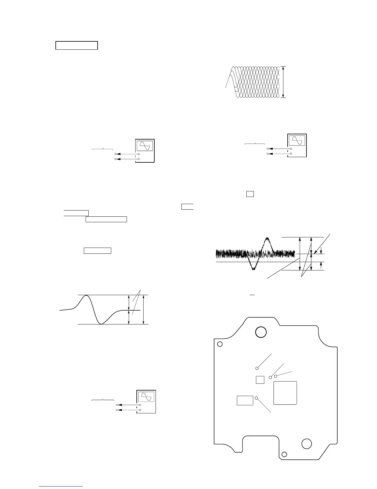
S Curve Check
Connection :
Procedure :
1. Connect an oscilloscope to test point TP (FE) and TP (DVC) on
the BD board.
2. Turn the power on.
3. Load the disc (YEDS-18).
4. Enter the test mode, select the BU Test asd press the l
AMS L (DECK B) knolo to display “bdt S CURVED”.
5. Press the l AMS L (DECK B) knob. “LD AL” is
displayed and playback starts automatically.
6. Check the oscilloscope waveform (S-curve) is symmetrical
between A and B. And confirm peak to peak level within 3.6 ±
0.5 Vp-p.
7. Press the MENU/NO button to stop playback.
8. Exit fromthe test mode.
(Refer to the TEST MODE Section)
Note: Try to measure several times to make sure than the ratio of A
: B or B : A is more than 10 : 7.
RF Level Check
Connection :
Procedure :
1. Connect an oscilloscope to TP (RFAC) and TP (DVC).
2. Turn the power on.
3. Load the disc (YEDS-18) and playback the number five track.
4. Confirm that oscilloscope waveform is clear and check RF signal
level is correct or not.
CD SECTION (DECK A)
Note: A clear RF signal waveform means that the shape “◊” can be
clearly distinguished at the center of the waveform.
E-F Balance (1 Track jump) Check
Connection :
Procedure:
1. Connect an oscilloscope to TP (TE) and TP (DVC).
2. Turn the power on.
3. Load the disc (YEDS-18) and playback the number five track.
4. Press the CD X (DECK A) button.
(Becomes the 1 track jump mode.)
5. Confirm the level B and A (DC voltage) on the oscilloscope
waveform.
Specification level: x 100=less than ±22%
[BD BOARD] — SIDE A —
A
B
VOLT/DIV : 200mV
TIME/DIV : 500ns
level : 1.1
±
0.3Vp-p
 Loading...