7-2
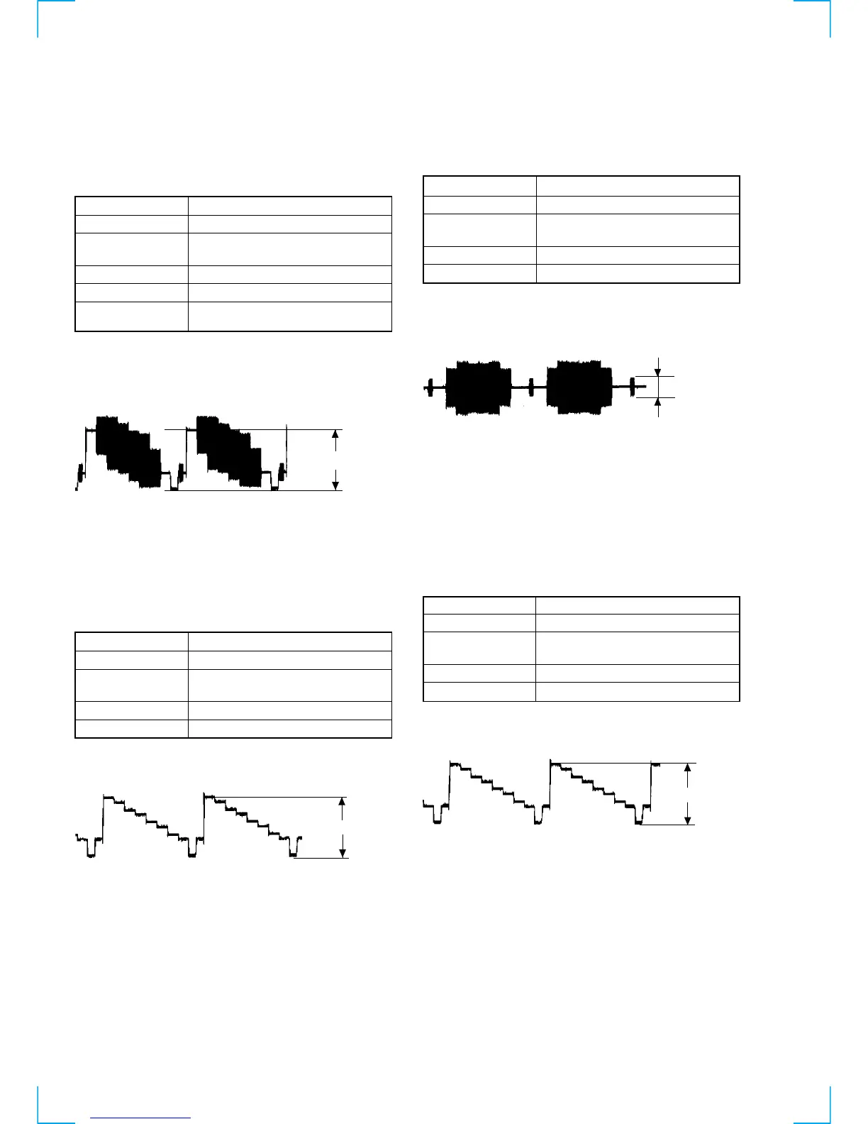
2-2. C Output Check (MB-94 BOARD)
<Purpose>
Checks S-terminal video output. If it is incorrect picture will not be
displayed correctly in spite of connection to the TV with a S-terminal
cable.
Mode Playback mode
Signal Color bars
Test point
S VIDEO OUT (S-C) connector
(75 Ω terminated)
Instrument Oscilloscope
Specification A=300 ± 100 mVp-p (PAL)
Checking method:
1) Confirm that the S-C burst is A=286 ± 30 mVp-p (NTSC),
A=300 mVp-p (PAL).
Fig. 8-3
3. Checking Component Video Output (MB-94 BOARD)
Note:
CONPONENT OUT should be set to ON in AEP, UK model.
3-1. Y Output level Check
<Purpose>
This checks component video output Y. If it is incorrect, correct
brightness will not be attained when connected to, for instance,
projector.
Mode Playback mode
Signal Color bars
Test point
COMPONENT VIDEO OUT (Y)
connector (75 Ω terminated)
Instrument Oscilloscope
Specification 1.00 ± 0.05 Vp-p
Checking method:
1) Confirm that the Y level is 1.00 ± 0.05 Vp-p.
Fig. 8-4
7-2. ADJUSTMENT OF VIDEO SYSTEM
1. Video Level Adjustment (MB-94 BOARD)
<Purpose>
This adjustment is made to satisfy the NTSC/PAL standard, and if
not adjusted correctly, the brightness will be too large or small.
Mode Video level adjustment in test mode
Signal Color bars
Test point
LINE OUT (VIDEO) connector
(75 Ω terminated)
Instrument Oscilloscope
Adjusting element RV501
Specification 1.00 Vp-p
Adjusting method:
1) In the test mode initial menu “6” Video Level Adjustment, set
so that color bars are generated.
2) Adjust the RV501 to attain 1.0 Vp-p.
Fig. 8-1
2. S-terminal
2-1. Y Output Check (MB-94 BOARD)
<Purpose>
Check S-terminal video output. If it is incorrect, pictures will not
be displayed correctly in spite of connection to the TV with a S-
terminal cable.
Mode Playback mode
Signal Color bars
Test point
S VIDEO OUT (S-Y) connector
(75 Ω terminated)
Instrument Oscilloscope
Specification 1.00 ± 0.05 Vp-p
Checking method:
1) Confirm that the S-Y level is 1.00 ± 0.05 Vp-p.
Fig. 8-2
+0.04
–0.02
+0.04
–0.02
1.00 ± Vp-p
+0.04
–0.02
1.00 ± 0.05 Vp-p
 Loading...