EasyManua.ls Logo

Sony RMT-D123A - Overall; Front Panel-1

Sony RMT-D123A
142 pages
Print Icon
To Next Page IconTo Next Page
To Previous Page IconTo Previous Page
Loading...
2-1
DVP-CX860/CX870D
SECTION 2
DISASSEMBLY
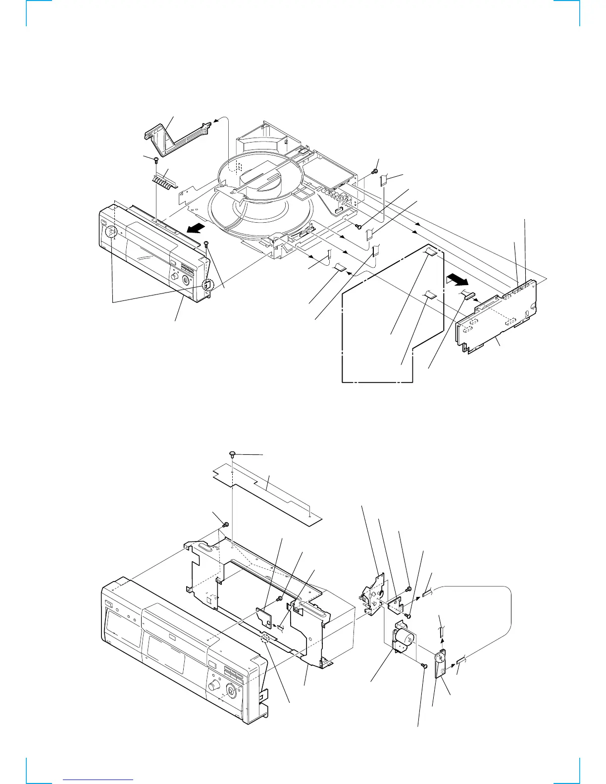
NOTE: Follow the disassembly procedure in the numerical order given.
2-1. OVERALL
1
Two screws
(+BV 3
×
10
)
3
Two screws (+BV 3
×
6
)
qs
Two screws (+BV 3
×
10
)
qd
Two screws (+BV 3
×
10
)
ql
Flat cable (CN501, 154p)
qg
Flat cable (CN005, 15p)
qj
Board to board connector (15p)
qf
Board to board
connector (15p)
qk
Flat cable
(CN004, 17p)
7
Flat cable
(CN204, 11p)
8
Flat cable
(CN103, 15p)
wa
AI board
section
5
Flat cable (CN308, 23p)
6
Flat cable
(CN103, 6p)
q;
Front panel section
qa
P-SW rod
2
Spring(H),
ground plate
qh
9
4
Two claws
w;
Harness (PA-137) (CN101, 15p)
DVP-CX860
(AEP,UK)
model
2-2. FRONT PANEL-1
qk Screw
(+BVTP
2.6
×
8
)
qj Flat cable
(CN301, 3p)
ql SW-345 board
1 Two screws (+BVTP
2.6
×
8
)
9 Screws (+BVTP
2.6
×
8
)
4 Two screws (+BVTP
2.6
×
8
)
qg Flexible cover
qf Two rivets
qh Front chassis
qd Claw
qs Six screws (+BVTP
2.6
×
8
)
7 DM-96 board
6 Remove the two solderings.
8 Driving gear
(B) block assy
qa Gear base plate (A) assy
q; DA-29 board
5 Flat cable
(CN501, 154p)
2 Flat cable (CN192, 4p)
3 Flexible flat cable (CN161, 4p)

Table of Contents