STR-DA6400ES
23
SECTION 4
TEST MODE
HISTORY MODE
The state that the set is used is memorized.
Procedure:
1. While pressing the [MUSIC] and joy stick enter buttons, press
the [POWER] button to turn on the power and “HISTORY
MODE” is displayed.
2. Each time up or down jog switch, the item is switched in order
as follows.
Items Display
Number of protector is gener-
ated
PRCT COUNT: XXX
Total use time TTL_TIME: XXXXH XXM
Sound fi eld XXXXXXXXXXXXXXXX
Input Selector INPUT: XXXXXXXXXX
Input mode INMODE: XXXXXXXXXXXX
Input mode under lock state DSEL: XXXXXXXXXXXXXXX
Stream under input STREAM: XXXXXXX
Channel information CONFIG:XXXXXXX
State of headphone HEAD PHONES: XXX
Volume VOL: XXXdB
EQ setting value
BASS: XXXdB
TREB: XXXdB
Level collection value
each channel
Lv FL/FR XXXX/XXXX
Lv SL/SR XXXX/XXXX
Lv CT/SW XXXX/XXXX
Lv BL/BR XXXX/XXXX
Total time of power on TTL_P_ON: XXXXH XXM
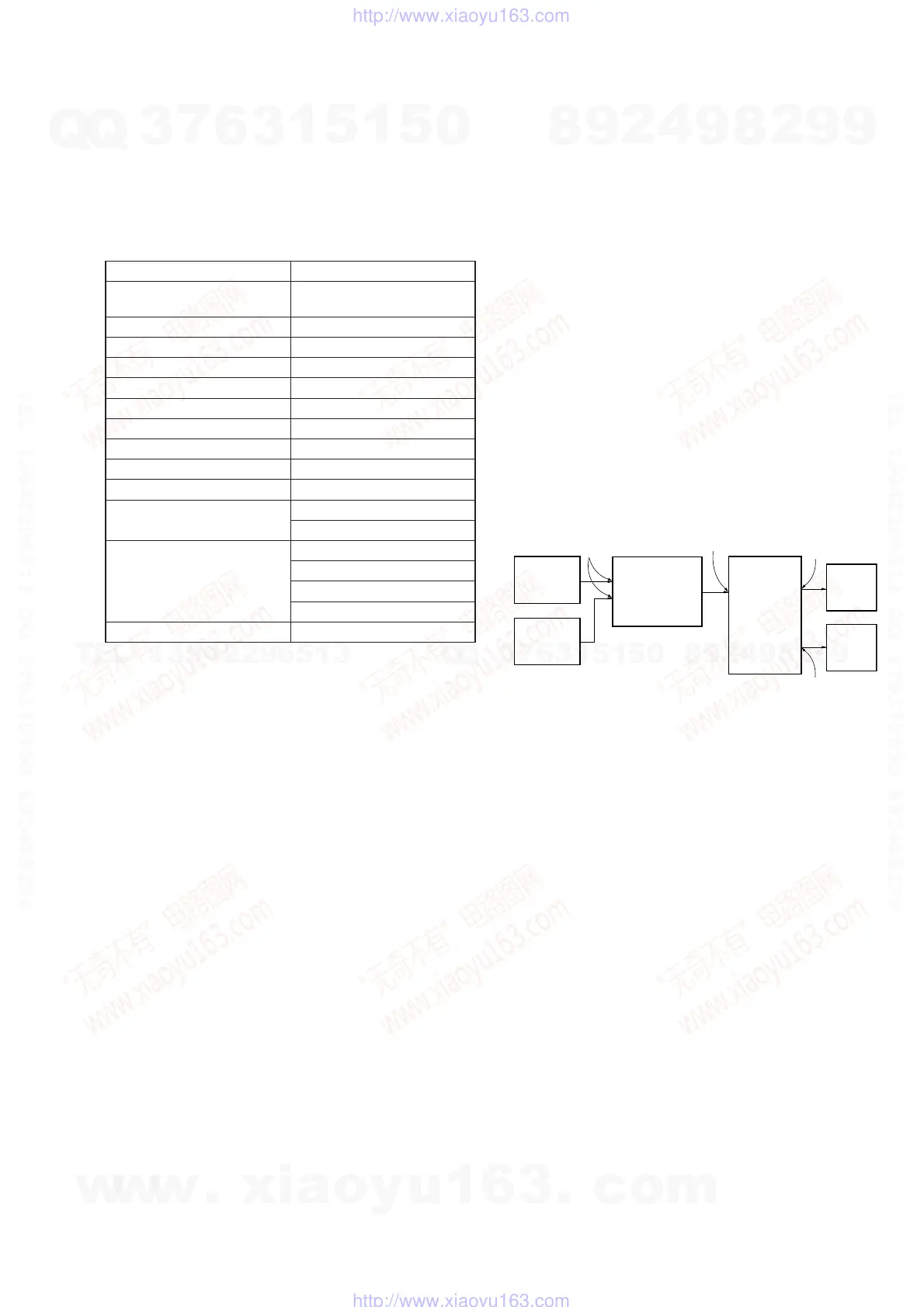
DIGITAL MEDIA PORT TEST
Procedure:
1. Connect the DMPORT check jig (Part No. J-2501-309-A) with
the DMPORT jack (CN6751) on the NETWORK board.
2. While pressing the [A.F.D.] and [MENU] buttons, press the
[POWER] button to turn on the main power.
3. The message “DMPORT OK.” appears on the fl uorescent indi-
cator tube and enter the digital media port test mode. (Confi r-
mation of communication line)
When “NO DETECT”, “UART NG” and “UART TO” are dis-
played on the fl uorescent indicator tube, confi rm the connec-
tion of the DMPORT check jig, and enter the mode again.
Each time the [
>] button on the remote commander is
pressed, the connect check and adaptor version check are
switched.
Press the [
.] button on the remote commander, connected
confi rmation of the DMPORT check jig is done again.
4. To a pinjack of the DMPORT check jig input information rele-
vant to audio signal (sine-wave 1.0V rms) and composite video
signal (white 100% 1.0Vp-p, color bar, etc.).
5. Confi rm the output of speakers and monitor TV. (Confi rmation
of analog signal)
6. To release from this mode, press the [
x] button on the remote
commander.
color
pattern
generator
DMPORT
check jig
(Part No.
J-2501-309-A)
J001
AF
oscillator
set
TV
monitor
FL/FR
speaker
NETWORK board
CN6751
MAIN board
TM4002
A-VIDEO board
J6001
XM FACTORY TEST MODE
Mode to confi rm operation of XM. Doing display of ID of XM
antenna and output of audio signal that XM antenna generates, it is
confi rmed that there are no problems in the communication of the
XM antenna and the transmission of the audio signal.
Procedure:
1. The XM antenna was connected, while pressing the [TUNING
MODE] and [MOVIE] buttons, press the [POWER] button to
turn on the main power.
2. Whenever the [DISPLAY] button is pressed, the output of the
audio signal of 1 kHz L/R, 20 Hz L/R, 5 kHz L/R, muting, 1
kHz L and 1kHz R are switched.
SIRIUS FACTORY TEST MODE
Mode to confi rm operation of SIRIUS. Doing display of ID of
SIRIUS antenna and output of audio signal that SIRIUS antenna
generates, it is confi rmed that there are no problems in the commu-
nication of the SIRIUS antenna and the transmission of the audio
signal.
Procedure:
1. The SIRIUS antenna was connected, while pressing the
[TUNING MODE] and [A.F.D.] buttons, press the [POWER]
button to turn on the main power.
2. Whenever the [DISPLAY] button is pressed, the output of the
audio signal of 1 kHz L/R, 20 kHz L/R, 10 Hz L/R, noise L,
noise R, muting are switched.
w
w
w
.
x
i
a
o
y
u
1
6
3
.
c
o
m
Q
Q
3
7
6
3
1
5
1
5
0
9
9
2
8
9
4
2
9
8
T
E
L
1
3
9
4
2
2
9
6
5
1
3
9
9
2
8
9
4
2
9
8
0
5
1
5
1
3
6
7
3
Q
Q
TEL 13942296513 QQ 376315150 892498299
TEL 13942296513 QQ 376315150 892498299
http://www.xiaoyu163.com
http://www.xiaoyu163.com