Do you have a question about the Sony VPL-S900E and is the answer not in the manual?
| Display Technology | 3 LCD |
|---|---|
| Lamp Type | UHP |
| Lamp Life | 2000 hours |
| Projection Size | 40 - 300 inches |
| Input Terminals | Composite, S-Video |
| Output Terminals | VGA |
| Noise Level | 35 dB |
Provides basic operating guidance for the projector models.
Guides dealers on the installation process of the projector.
Details the operating procedures for the IFB-X600E interface board.
Covers the installation procedures for the PSS-600 projector suspension.
Identifies the physical location of circuit boards within the projector.
Outlines the steps required to disassemble the projector unit.
Describes the procedure for adjusting the VCOM signal for optimal performance.
Details how to adjust signal levels for various inputs like RGB and Video.
Presents the overall schematic of the projector's frame.
Provides detailed schematics and printed wiring board layouts.
Provides basic operating guidance for the projector models.
Essential safety and handling information before operating the projector.
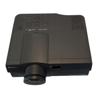
Highlights the key capabilities and technical aspects of the projector.
Identifies all projector controls and their functions.
Instructions for physically setting up the projector.
Guides on connecting external devices like computers and VCRs.
Steps for starting and managing the projection process.
Explains how to navigate and use the projector's on-screen menu.
Provides visual examples of typical projector installations.
Instructions for maintenance tasks like filter cleaning and problem resolution.
Lists technical specifications and an index of manual topics.
Crucial safety guidelines for handling and operating the projector.
Advice on lighting and ventilation to prevent overheating.
Steps for maintaining the projector's cleanliness and repacking it.
Details on the projector's visual performance capabilities.
Explains user-friendly setup functions and presentation features.
Information on the projector's lightweight design and input signal support.
Identifies and explains the functions of controls and indicators on the projector's front.
Instructions on using the carrying handle and attaching/removing the front cover.
Steps for installing the remote and adjusting projector height.
Explains the operation of each button on the projector's control panel.
Description of what the various status indicators on the projector signify.
Identifies rear panel controls like adjusters and connector ports.
Explains the function and connection of various input/output jacks.
Details on using the remote for computer control and laser pointer.
Instructions for setting up the projector on a flat surface.
Guidelines for mounting the projector on a ceiling.
Provides tables and formulas for calculating projection distances.
Step-by-step guide for connecting the projector to a computer.
Explains how to use the remote commander for computer mouse functions.
Instructions for connecting video sources like VCRs and RGB equipment.
Explains how to use the RGB IN/OUT connector for monitor output.
Steps for turning on the projector and selecting the input source.
How to adjust focus, zoom, and get the clearest picture.
Functions for temporarily muting audio or cutting off the picture.
Steps to open, select, and adjust menu items.
How to clear the menu display and reset adjusted items.
Information on memory settings and behavior with no input signal.
How to adjust contrast, brightness, and color intensity for optimal picture appearance.
Fine-tuning skin tones, sharpness, and dynamic picture effects.
Options for gamma correction, color temperature, and system selection.
Lists which picture settings are adjustable for different input signals.
Adjusting dot phase for clarity, picture size, and position.
Options for adjusting aspect ratio and using the scan converter.
Information on selecting input signals and using preset memory settings.
Controls for on-screen display status and input selection.
Options for changing menu language and picture orientation.
Controls for speaker output and power saving features.
Options for configuring the remote control receivers.
Detailed measurements for setting up the projector on the floor.
Procedures and considerations for ceiling-mounted installations.
Hazards associated with blocking ventilation holes and inadequate airflow.
Dangers of installing in environments with extreme temperature or humidity.
Problems caused by dust accumulation and air filter obstruction.
Precautions against toppling and ensuring the unit is level.
Warnings against covering ventilation holes to prevent heat buildup.
Information on when to replace the projector lamp.
Detailed steps for cleaning the air filter to maintain performance.
Solutions for issues like no power, no picture, or no sound.
Troubleshooting for incorrect input selection or SET SETTING menu configuration.
Solutions for on-screen display problems and incorrect color balance.
Clarifies meanings of caution messages like 'NO INPUT' and 'High Temperature'.
Details on the projector's optical system, including LCD panels, lens, and lamp.
Information on color systems, resolution, and input/output specifications.
Specifications for the built-in speaker system and power consumption.
Details on operating temperature, humidity, and included accessories.
Pin configurations for various connectors like RGB and MOUSE.
Details for mouse cables and signal adapter switch positions.
Provides detailed measurements of the projector unit in various views.
Shows dimensions for the assembled projector mounting bracket.
Covers manual topics from A to D for quick reference.
Covers manual topics from E to K for quick reference.
Covers manual topics from L to Q for quick reference.
Covers manual topics from R to Z for quick reference.
Provides the installation manual in English, French, and Spanish.
Crucial safety guidelines for handling and operating the projector.
Guidelines for safe and correct physical installation.
Advice on managing lighting and ventilation to prevent overheating.
Instructions for maintaining the projector's cleanliness and repacking it.
Describes the scope of the manual regarding installation and lens replacement.
Step-by-step instructions for removing and installing projector lenses.
Important tips for handling lenses to prevent scratches and damage.
Instructions for adjusting the lens position for zero optical axis angle.
Tables and formulas for calculating dimensions for front projection floor installs.
Tables and formulas for calculating dimensions for ceiling installs.
Explains the formulas used to calculate installation measurements.
Specific measurements and calculations for ceiling installations.
Installation data for specific lenses and signal types on various projector models.
Measurements for rear projection floor installations with zero optical axis angle.
Installation measurements for the standard lens on VPL-X600U/E/M.
Installation measurements for the VPLL-FM20 fixed short focus lens.
Installation data for VPL-X1000 projector with VPLL-ZM100 lens.
Installation data and calculation methods for VPL-S900 projector.
Provides operating instructions for the IFB-X600E interface board.
Step-by-step instructions for mounting the interface board onto the projector.
Explains the function and connection of S VIDEO and VIDEO IN jacks.
Details the connection and use of AUDIO IN jacks for stereo and monaural equipment.
Technical details for video and audio input signals.
Lists included accessories like audio/video cable and screwdriver.
Manual for installing the PSS-600 projector suspension support.
Crucial safety guidelines for handling and installing the projector.
Lists parts for the upper ceiling mount bracket and adjustment pipes.
Lists parts for the projector mount bracket, bolts, screws, and washers.
Shows the side and top view dimensions of the projector.
Details dimensions of the projector's bottom, front, and rear views.
Illustrates the side view setup for projector installation.
Shows the top view setup for projector installation.
Illustrates the front and bottom views of attaching the projector to the ceiling mount.
Step-by-step instructions for attaching the projector to the ceiling mount.
Illustrates projector installation on a wooden ceiling structure.
Provides formulas for calculating floor installation measurements.
Examples of projector installation on different floor types.
Illustrates projector installation on a concrete ceiling structure.
Details the dimensions of various mounting bracket and pipe components.
Information on the weight of the bracket and its maximum loading capacity.
Visual representation of the location of major circuit boards within the projector.
Steps for removing the main projector cabinet assembly and front panel.
Instructions for removing the scan converter unit and GA/U circuit boards.
Procedure for removing the power supply block and the F circuit board.
Instructions for removing the connector panel and related circuit boards.
Steps for removing C board, optical unit, and GB/GBA/V boards.
Procedure for removing the BA and BAA circuit boards.
Step-by-step guide for removing and adjusting the projector lens.
Instructions for removing and adjusting the prism block and condenser lenses.
Steps for adjusting VCOM levels to minimize flicker in video signals.
Procedure for adjusting RGB and video signal levels to meet specifications.
Procedure for adjusting composite video and video sub hue/color settings.
Explains the organization of memory blocks and differences from the 600 series.
Default settings for picture control and input settings menus.
Default settings for projector setup and white balance.
Lists various integrated circuits and transistors used in the projector.
Lists various diode types utilized in the projector's circuitry.
Detailed illustration of the projector's cabinet components and their assembly.
Lists all individual parts that make up the projector's cabinet assembly.
Illustration showing the internal chassis components and their layout.
Lists all individual parts that make up the projector's chassis.
Illustration showing the projector's base components and their assembly.
Lists all individual parts that make up the projector's base assembly.
Detailed illustration of the projector's optical components and their assembly.
Lists all individual parts that make up the projector's optical unit.
Details on resistor values, tolerance, and flammability.
Details on capacitor values, type, and voltage rating.
List of capacitors and connectors on the BA board.
List of diodes and integrated circuits on the BA board.
Lists integrated circuits, coils, and filters on the BA board.
Lists transistors and resistors on the BA board.
Lists integrated circuits, coils, and transistors on the BA board.
List of resistors on the BA board with values and specifications.
Continuation of the resistor list for the BA board.
Lists capacitors, connectors, and diodes on the BAA board.
Lists integrated circuits and transistors on the BAA board.
Lists resistors and crystals on the BAA board.
Lists capacitors, connectors, and diodes on the BAA BB board.
Lists integrated circuits and transistors on the BAA BB board.
List of resistors on the BAA BB board.
Lists capacitors, connectors, and diodes on the BB C board.
Lists integrated circuits and transistors on the BB C board.
List of capacitors on the C board.
List of connectors on the C board.
List of diodes on the C board.
List of integrated circuits on the C board.
Continuation of the list of integrated circuits on the C board.
List of resistors on the C board.
Lists capacitors, connectors, diodes, ICs, transistors, and resistors related to F and GA sections.
Lists capacitors, connectors, diodes, ICs, coils, photo couplers, transistors, and resistors on the GA board.
Continuation of the resistor list for the GA board.
Lists capacitors, connectors, diodes, ICs, transistors, and resistors on the GB board.
Lists components on the GBA board.
Schematic details for the GBA board's regulator and fan protection circuits.
First part of the BB board schematic focusing on memory control for the R channel.
Second part of the BB board schematic focusing on memory control for the G channel.
Third part of the BB board schematic focusing on memory control for the B channel.
Fourth part of the BB board schematic focusing on memory control (C3).
Fifth part of the BB board schematic focusing on memory control (C3).
Sixth part of the BB board schematic, detailing the RGB decoder circuit.
Shows the functional block diagram and signal flow between BA and QB boards.
Illustrates the first half of the BB board's functional block diagram.
Continues the functional block diagram for the BB board.
Shows the block diagram illustrating signal flow between these boards.
Focuses on the C board's internal block structure and connections.
Illustrates the functional block diagram and signal flow between these boards.
Shows the complete schematic diagram of the projector's frame and major components.
Detailed electrical schematic diagrams and printed wiring board layouts for the QA board.
Specific circuit details for IC1001, IC1006, and IC1009 on the QA board.
Identifies the location of components on the QB and QC boards.
Detailed schematic for the QC board, including IC and transistor connections.
Identifies component locations on the BA board.
Identifies component locations on the B-side of the BA board.
Detailed schematic for the first part of the BA board.
Detailed schematic for the second part of the BA board.
Detailed schematic for the third part of the BA board.
Illustrates waveforms and shows internal schematics for key ICs on the BA board.
Provides schematics for ICs and transistors on the BA board.
Detailed schematics for the NF, NR, U, and V circuit boards.
Detailed schematic for the first section of the C board.
Schematics for ICs and components on the second section of the C board.
Schematics for ICs and components on the third section of the C board.
Schematics for ICs and components on the fourth section of the C board.
Schematics for ICs and components on the fifth section of the C board.
Detailed schematic of the C board, covering various sections.
Illustrates waveforms for the second part of the C board schematic.
Illustrates waveforms for the third part of the C board schematic.
Illustrates waveforms for the fourth part of the C board schematic.
Identifies component locations on the H board.
Shows the schematic for the H board's control panel interface.
Identifies component locations on the BAA board.
Identifies component locations on the QD board.
Shows schematics for ICs and transistors on the BAA board.
Identifies component locations on the GA board.
Identifies component locations on the F board.
Schematic details for the GA board's power factor control circuit.
Schematic details for the F board's AC input and rectifier circuit.
Identifies component locations on the GB board.
Schematic details for the GB board's power supply circuitry.
Identifies component locations on the GBA board.
Schematic details for the GBA board's regulator and fan protection circuits.
First part of the BB board schematic focusing on memory control for the R channel.
Second part of the BB board schematic focusing on memory control for the G channel.
Third part of the BB board schematic focusing on memory control for the B channel.
Fourth part of the BB board schematic focusing on memory control (C3).
Fifth part of the BB board schematic focusing on memory control (C3).
Sixth part of the BB board schematic, detailing the RGB decoder circuit.