SS2000 Operator’s Manual
H
2
S in Natural Gas 2–5
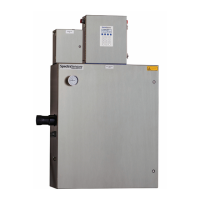
3. For AC systems, pull ground, neutral and hot wires into the control
box. For DC systems, pull ground, plus and minus wires.
4. Strip back the jacket and/or insulation of the wires just enough to
connect to the power terminal block.
5. For AC systems, attach the neutral and hot wires to the power
terminal block by connecting the neutral wire to the terminal marked
“NEU,” the hot wire to the terminal marked “LINE,” as shown in
Figure 2–1. For DC systems, connect the minus line to the terminal
marked “−,” and the positive line to the terminal marked “+,” as
shown in Figure 2–2.
6. Connect the ground wire to the ground terminal marked .
An approved switch or circuit-breaker rated for 15 amps should
be used and clearly marked as the disconnecting device for the
analyzer.
VALVE &
ALARM
RELAYS
(if applicable)
VALVE &
ALARM
RELAYS
(if applicable)
LINE
NEU
Figure 2–1 AC connection terminal block in control
box.
 Loading...