SS2000 Operator’s Manual 4–1
4 - GAS SAMPLE CONDITIONING
S
YSTEM - H
2
S IN NATURAL GAS
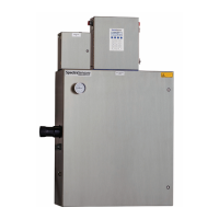
About the Sample Conditioning System
The SS2000 analyzer for measuring H
2
S in natural gas comes equipped with
an integral sample conditioning system, as illustrated by the flow schematic in
Figures 4–1 and 4–2. Because of the important role the sample conditioning
system plays in the analysis, care should be taken to install and maintain the
system in order to ensure optimum performance.
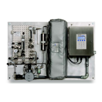
As shown in Figures 4–1 and 4–2, sample gas enters the sample conditioning
unit at the sample inlet port [inlet pressure of 30 psig (2.1 barg) max set by a
customer-supplied upstream regulator], passes through a shut-off valve and
particle filter and into a membrane separator, where any liquid in the stream is
removed. Liquid removed by the membrane separator is sent through the
bypass loop and out the bypass port. A continuous flow (set by a metering
valve and flow meter of 0.5 lpm) through the bypass loop not only flushes any
accumulated liquid, but also maintains a continuous flow through the often
relatively long sample lines which reduces sample variation due to adherent
species. A relief vent attached to the bypass via a relief valve [set for 50 psig
(3.4 barg)] protects the entire system from any overpressure condition. There
is also a sample port for convenience.
Once the sample gas passes through the membrane separator, it proceeds to
a set of solenoid switching valves connected to the analyzer control
electronics.The switching valves direct the flow either directly to the analyzer
(wet cycle), or through a H
2
S scrubber and on to the analyzer (dry cycle). The
reason for the two flow paths is that the H
2
S spectrum overlaps a strong
resonance of a component of the background gas (the concentration of which
is unknown) which causes interference in the measurement. When the analyzer
detects a change in the background signal, the flow is sent through the H
2
S
scrubber for a measurement of the flow without H
2
S (the analyzer
automatically switches back and forth between the two streams as required).
This measurement yields the amount of signal attributable to the background
gases. Subtracting this background contribution from the normal measurement
results in a signal that is proportional only to the desired H
2
S concentration.
As the flow leaves the switching valves, a pressure regulator [set at 10 psig
(0.7 barg)], metering valve and flowmeter control the flow into the analyzer.
The flow exiting the analyzer is sent out the sample return port to be vented
to a safe location.
Operating the Sample Conditioning System
The sample conditioning system is factory set with the appropriate pressures
and flow rates, as indicated in Figures 4–1 and 4–2. Under normal operating
conditions, the sample conditioning system should operate autonomously.
 Loading...