Installation
2–12 H
2
S in Natural Gas
8. Reinsert the mating terminal block into its base and verify that each
connection is secure.
9. Strip back the jacket and insulation of the alarm cables just enough
to connect to the appropriate relays shown in Figure 2–5. The top
tier connection is normally open, the middle common and the
bottom normally closed. Choose either normally open or normally
closed to fit your particular control scheme.
10. Close and tighten the control box cover.
11. To complete the connections, connect the other end of the current
loop wires to a current loop receiver, the external serial cable to a
serial port on your computer, and the digital output cables to the
appropriate switches or relays in your control system.
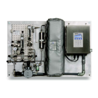
Connecting the Gas Lines
Once you have verified that the analyzer is functional and that the analyzer
circuit is de-energized, you are ready to connect the inlet, outlet, and validation
source (if applicable) gas lines. Consult the layout and flow diagrams in
Appendix B for guidance. All work must be performed by technicians qualified
in pneumatic tubing.
SpectraSensors recommends using 1/4” O.D x .035” wall thickness, welded or
seamless stainless steel tubing. Refer to the system layout drawing in Figure
B–1 on page B–2 for inlet and outlet port locations.
Table 2–1 Output/Input signal connections.
Terminal Description D-Conn Color
1 Ch. A Serial RX Pin-3 Black
2 Ch. A Serial TX Pin-2 Red
3 COM Serial Ground Pin-5 Shield
4Not Used
5Not Used
6 Ch. A Current Loop +
7 Ch. A Current Loop -
8Not Used
9Not Used
10 Not Used
11 Not Used
12 Not Used
 Loading...