Section 4—Installation Power-Style™ QED-2 Switchboards
19© 1988–2018 Schneider Electric All Rights Reserved80043-055-13
ENGLISH
Anchoring QED-2
Equipment for Seismic
Applications
Formed base channels run the width of the section. The channels and connecting
braces provide a minimum 0.75-in. (19 mm) diameter hole for fastening the section
to the floor. To anchor the QED-2 switchboard to the floor properly, use all four
mounting locations for NEMA Type 1 enclosures less than 36 in. deep, all six
mounting locations for 36–70 in. deep enclosures, and six of the eight mounting
locations for enclosures greater than 70-in. deep (see Figure 9 on page 21).
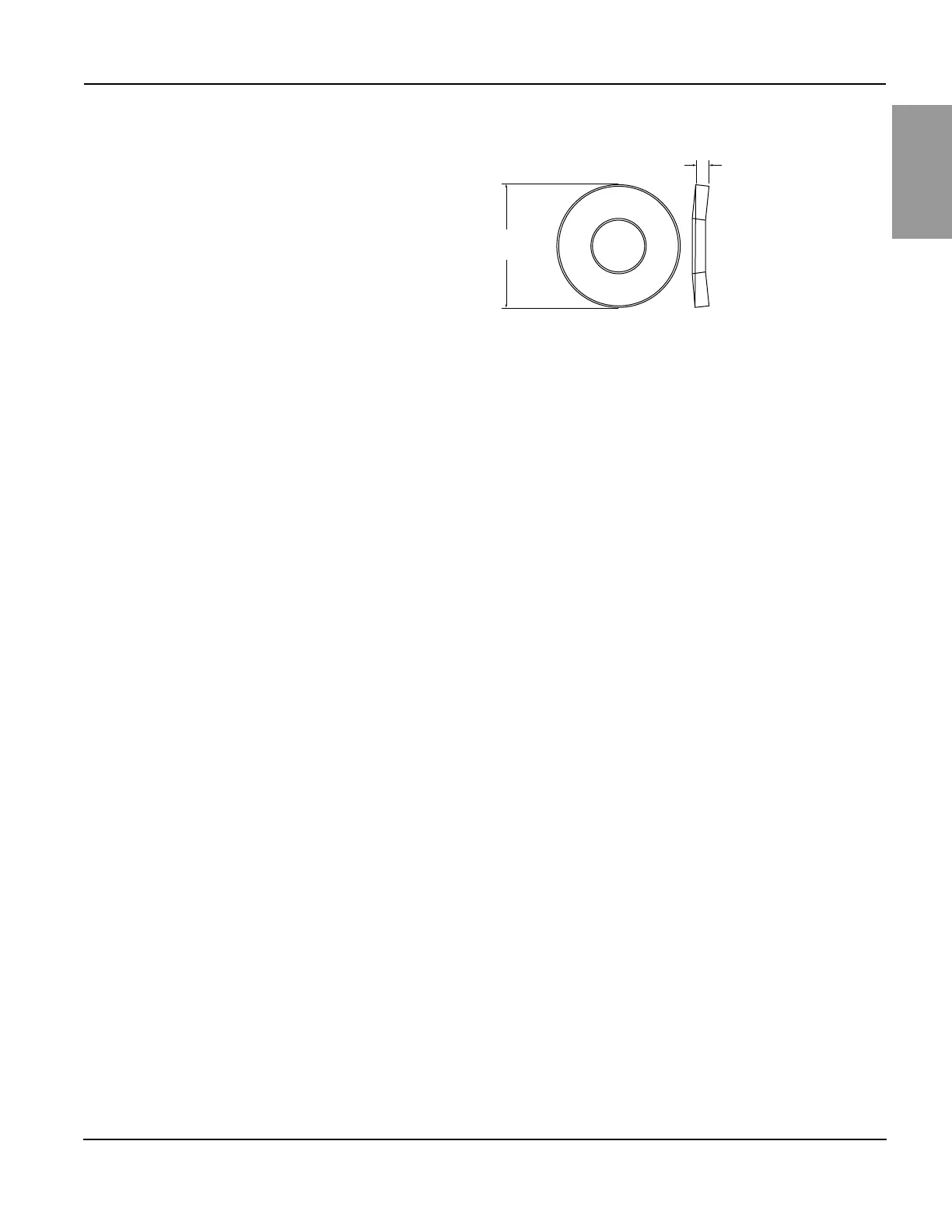
Use one 1.25 in. (32 mm) outer diameter Belleville washer (provided by others; see
Figure 8) under the head of each bolt or anchor nut. Additionally, each NEMA Type 1
enclosed section includes four top-located hard points for attaching two upper lateral
braces (braces and hardware supplied by others) to the QED-2 structure for top
structural restraint (see Figures 11 and 12 on page 23).
Top structural restraint is required for QED-2 equipment installed:
• when indicated by the seismic qualification certificate, or
• when displacement at the top of the equipment cannot be tolerated.
NOTE: Anchoring hardware is not furnished with the QED-2 equipment.
After the QED-2 switchboard and adjacent equipment are properly joined and the
entire structure is bolted to the floor, install the incoming service conductors and load
side cables. During an earthquake, the top of the QED-2 switchboard can move in
any direction. Any top incoming cables must accommodate this motion. Do not use
the QED-2 enclosure (particularly the top) to mount exterior equipment.
Figure 8 – Belleville Washer
ø 1.25 in.
(32 mm)
0.14 in.
(3.6 mm)