Section 4—Installation Power-Style™ QED-2 Switchboards
21© 1988–2018 Schneider Electric All Rights Reserved80043-055-13
ENGLISH
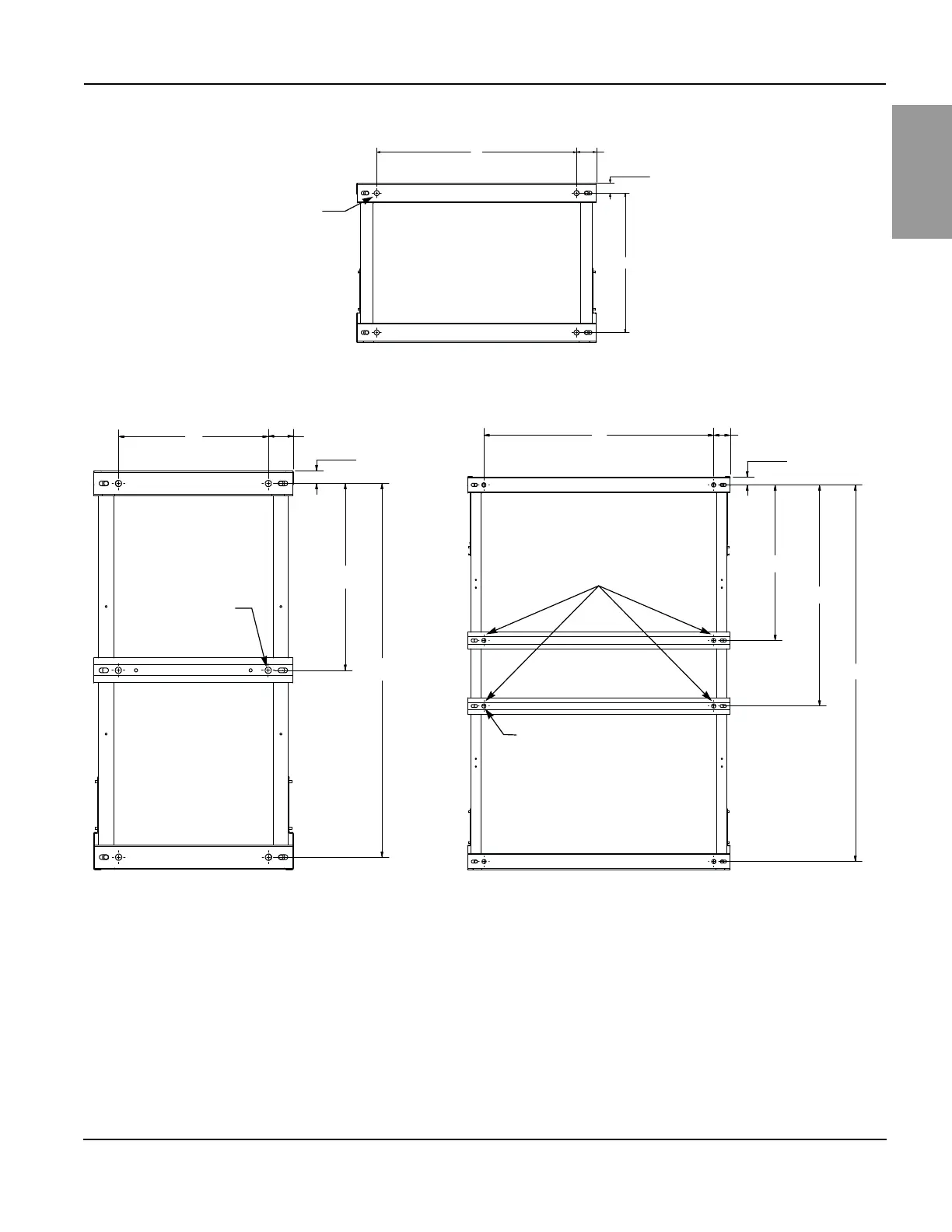
Figure 9 – Base Channel Floor Anchor Bolt Locations
X
Y
X
Y
Z
X
Y
Z
Z
1
2
Bottom View of Enclosure
Front of Enclosure
0.75 in. (19 mm) diameter
mounting holes (four places)
Enclosures < 36 in. Deep
3.0 in. (76 mm) (typical)
1.5 in. (38 mm) (typical)
Front of Enclosure
Enclosures > 70 in. Deep
3.0 in. (76 mm) (typical)
1.5 in. (38 mm)
(typical)
Front of Enclosure
0.75 in. (19 mm)
diameter mounting
holes (six places)
Enclosures 36–70 in. Deep
3.0 in. (76 mm) (typical)
1.5 in. (38 mm)
(typical)
0.75 in. (19 mm) diameter
mounting holes (eight places)
For configurations with two interior
located base channels, select one of the
channels and equip with two anchor
bolts for seismic applications.
Bottom View of Enclosure
Bottom View of Enclosure
NOTE: See Table 1
on page 20 for X, Y, Z
dimensional values.