Power-Style™ QED-2 Switchboards Section 4—Installation
22 © 1988–2018 Schneider Electric All Rights Reserved 80043-055-13
ENGLISH
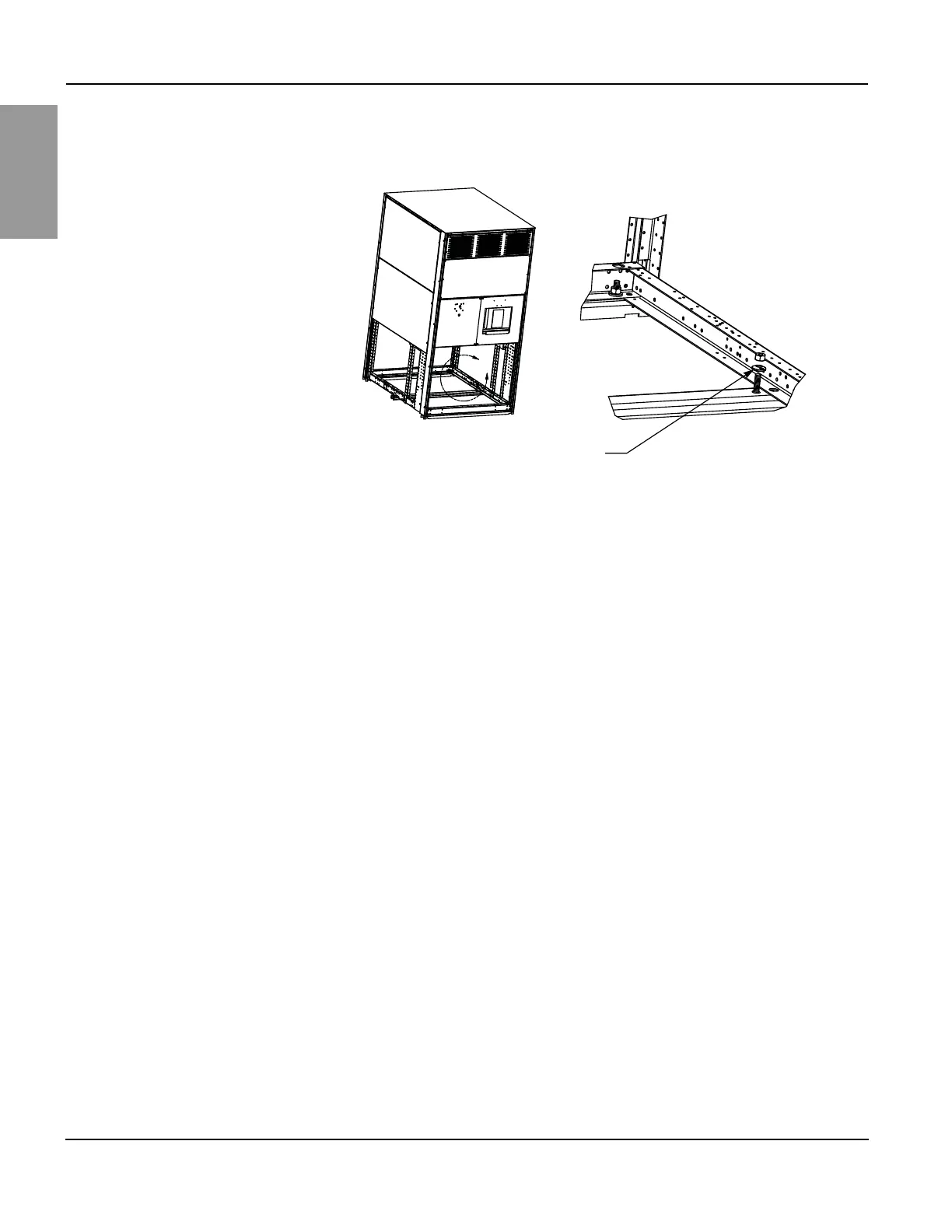
2. Depending on the frame size (see Figure 9 on page 21), use either four or six
anchorage points in the locations shown in Figure 10.
3. Once the switchboard is in place, secure the base channels. The hardware
used at each anchorage point must include a 1.25 in. (32 mm) diameter
Belleville washer, as illustrated in Figure 10.
NOTE: The “TOP” side of the Belleville washer must be facing up.
Top Anchoring/Restraint For installation at locations indicated by the seismic qualification certificate, or
where displacement cannot be tolerated at the top of the switchboard during a
seismic event, use top restraints attached to the equipment hard points.
NOTE: Anchoring hardware is not furnished with the switchboard.
1. The four 0.88-in. (22 mm) diameter mechanical knock-outs shown in Figure 11
on page 23 serve as hard points for application of a top restraint system.
NOTE: By code, it is the responsibility of the design engineer of record to
determine the top restraint methodology for the intended building
application.
Figure 10 – Base Channel Mounting Hardware
A
1.25 in. (32 mm) diameter Belleville washer
(TOP side facing up)
Detail A
NOTE: Base channel mounting
hardware detail shown for reference
purposes only. Anchoring hardware is
not furnished with the switchboard.
Covers and internal hardware shown
removed for illustration purposes.