Section 4—Installation Power-Style™ QED-2 Switchboards
29© 1988–2018 Schneider Electric All Rights Reserved80043-055-13
ENGLISH
5. Use an 18-in. (457 mm) or longer wrench to torque the joint bolt until the outer
break-away head twists off. Do not allow the break-away bolt head or red
warning disc to drop into the switchboard.
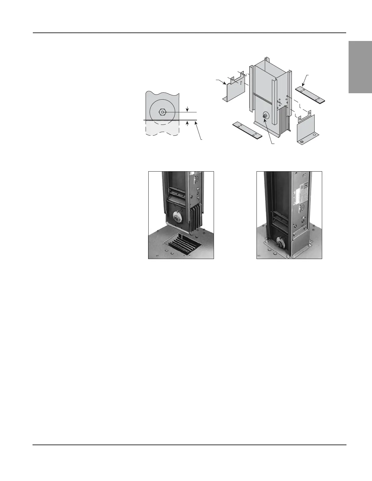
6. Slip the remaining two small closing plates into position by aligning with the holes
in the switchboard. Use the four 1/4-20 screws provided to secure the equipment.
7. Confirm proper phasing of the installed busway before energizing.
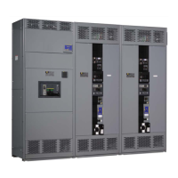
Figure 20 – Qwik Flange Installation
Figure 21 – Qwik Flange
Side closing plate
(2 required)
C/L of joint bolt
connection of
busway
Surface of
switchboard
Joint bolt
Small
closing
plate
0.95 in. (24 mm)