Section 4—Installation Power-Style™ QED-2 Switchboards
25© 1988–2018 Schneider Electric All Rights Reserved80043-055-13
ENGLISH
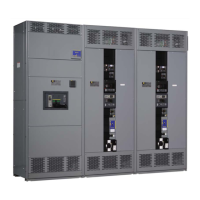
NOTE: The U-shaped connector will fit snugly against the insulating tube when
installed correctly. It is pulled away from the insulating tube in Figure 14 to
show the orientation of the connector slot.
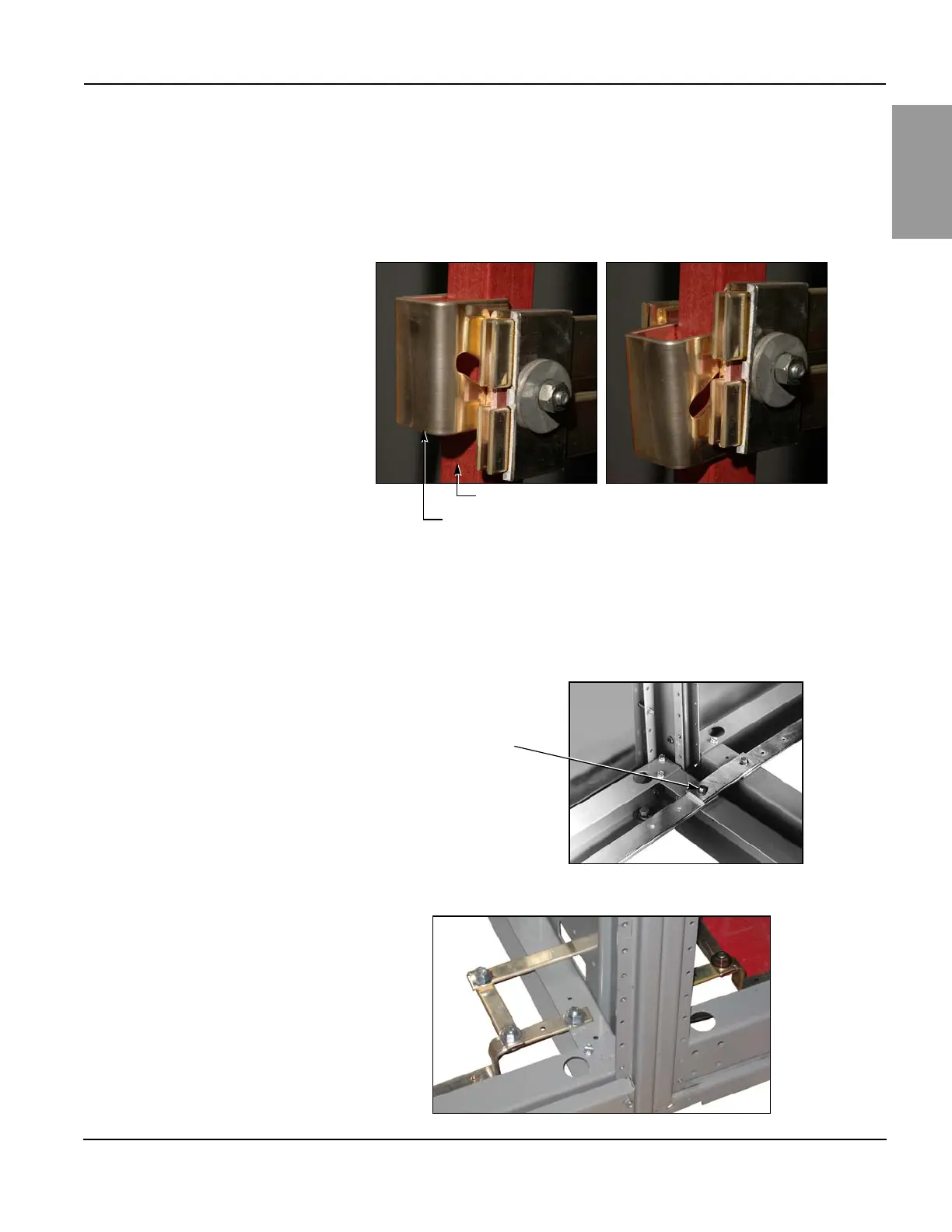
Ground Bus Splice Connections
Align and secure the ground bus splice connection between shipping sections.
Torque connections to 100 lb-in (11 N•m) (Figure 15 or 16).
NOTE: Proper installation is essential for equipment ground fault systems.
Figure 14 – Proper Orientation of U-shaped Splice Connector
Correct
Slot in splice connector
points downward.
Incorrect
Slot in splice connector
points upward.
U-shaped splice connector
Insulating tube
Figure 15 – Ground Bus Splice Connection
Figure 16 – Series 2 Ground Bus Splice Connection
Ground bus splice
(1/4-20 thread-forming
hardware provided)