120-52 January, 2016
Model F120 UV/IR Flame Detector
Latching Mode for the Delayed Alarm
The ame detector’s Delayed Alarm latching mode can be set as non-latching or latching.
Default Setting
The factory default setting for the Delayed Alarm is NON-LATCHING. This means that
when the detector no longer detects any re, the Delayed Alarm contacts will reset
automatically.
Switch # 4 Description
DOWN Sets the Delayed Alarm to NON-LATCHING. The Delayed Alarm
contacts will reset automatically when the ame detector no longer
sees any re.
Changing the Latching Mode for the Delayed Alarm
9. To change the Latching Mode for the Delayed Alarm contacts, follow the table below to
adjust the DIP Switch settings.
Switch # 4 Description
DOWN Sets the Delayed Alarm to NON-LATCHING. The Delayed Alarm
contacts will reset automatically when the ame detector no longer
sees any re. (Default Setting)
UP Sets the Delayed Alarm to LATCHING. In this mode, you must acti-
vate the manual reset input on the ame detector to clear the alarm.
If setting the Delayed Alarm contacts to LATCHING, make sure to install a RESET button
(not provided) to allow for the manual reset of the detector to clear the alarm. Terminal # 4
has been provided to wire a RESET button to the detector.
Install the New Electronics Module
10. Check the position of all wires on the terminal blocks inside the rear housing. Make
sure that all wires to the terminal blocks are properly secured so that they do not
interfere when the plug-in module is inserted. The wires must not protrude upward,
above the terminal blocks.
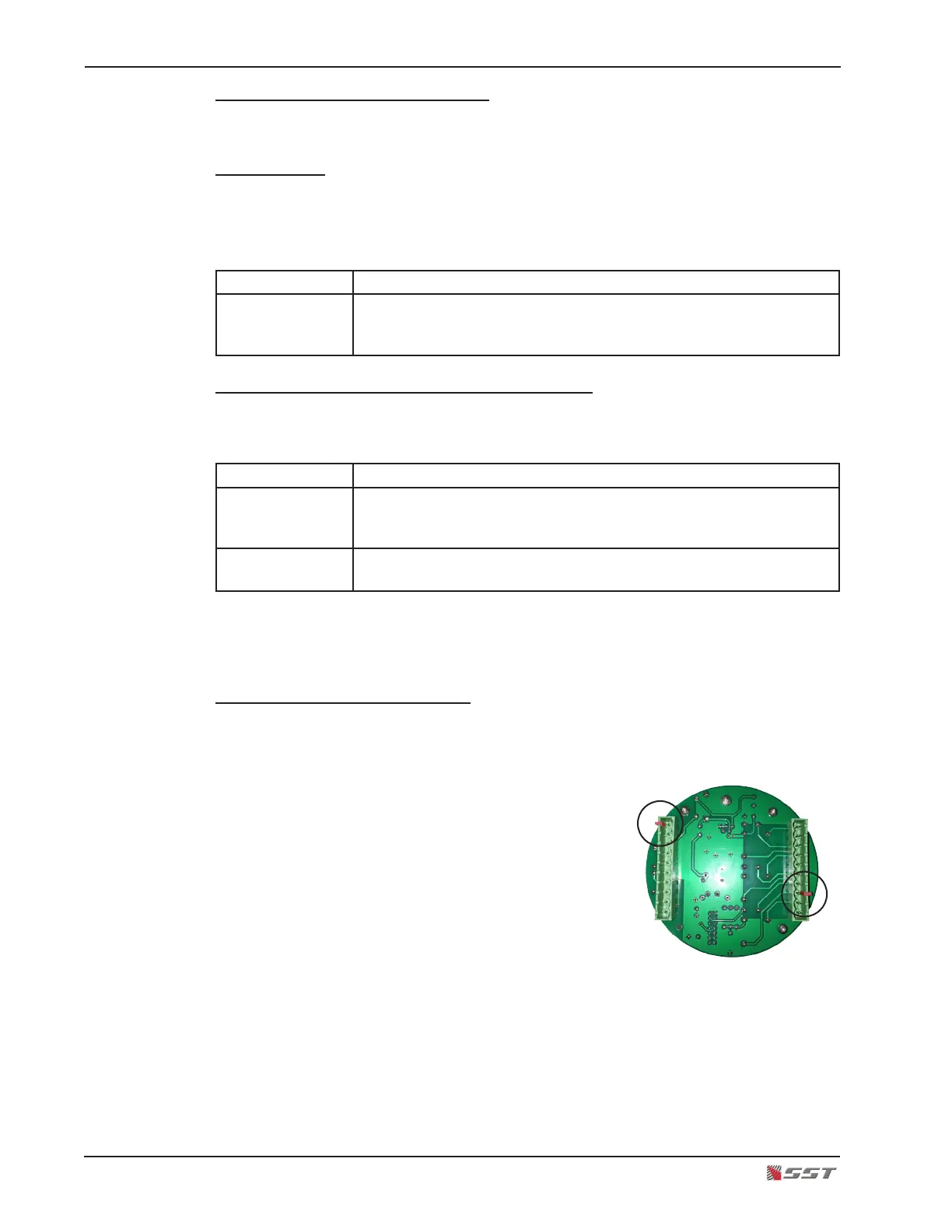
11. Connect polarized terminal blocks.
The mating terminal blocks of the electronics module
and the rear housing each have protective (RED) polar-
izing keys. This key is used to protect against improper
mating of the terminal blocks.
!
CAUTION: The RED key of the Electronics Module
WILL NOT FIT over the Red Key of the rear housing
connector. Orient the electronics module so that the Red Keys are NOT aligned.
Do not force the electronics module or damage may occur to the terminal blocks.
12. Plug the new electronics module.
13. Secure the electronics module in place by placing a thumb over each screw head on
the top PC board of the electronics module and gently push the electronics module in
place. Make sure the module is rmly secured on the rear housing terminal blocks.