UM2469 Rev 1 15/59
UM2469 Hardware layout and configuration
58
7.3.2 ST-LINK/V2-1 firmware upgrade
The ST-LINK/V2-1 embeds a firmware upgrade mechanism for in-situ upgrade through the
USB port. As the firmware may evolve during the life time of the ST-LINK/V2-1 product (for
example a new functionality, bug fixes, support for new microcontroller families), it is
recommended to visit the www.st.com website before starting to use the STM32F7308-DK
board and periodically, to stay up-to-date with the latest firmware version.
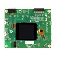
7.4 Power supply
The STM32F7308-DK board is designed to be powered from a 5 V DC power source. It is
possible to configure the STM32F7308-DK board to use any of the sources described in the
following
Table 2.
Note: The Discovery board must be powered by a power supply unit or by an auxiliary equipment
complying with the standard EN-60950-1: 2006+A11/2009, and must be Safety Extra Low
Voltage (SELV) with limited power capability.
7.4.1 Supplying the board through the ST-LINK USB port (default setting)
To power the STM32F7308-DK board in this way the USB host (PC) gets connected with
the ST-LINK USB port through a USB Type-A to Micro-B cable.
5 V DC power is provided by V
BUS
from the USB type Micro-B connector (CN1) of ST-
LINK/V2-1 (USB 5
V power source on silkscreen “ST-LINK”, see Figure 8). If the
USB
enumeration succeeds (as explained below), the ST-LINK 5 V link power is
enabled by
asserting the PWR_ENn signal. This pin is connected to U1, a power switch
ST890, which
powers the board. This power switch also features a current limitation to protect the PC in
case of a short-circuit on the board (current demand exceeding 700
mA).
The STM32F7308-DK board can be powered from the ST-LINK USB connector CN1
(STLINK), but only the STM32F103CBT6 (U2) is powered before USB enumeration,
because the host PC only provides 100
mA to the board at that time. During the USB
enumeration, the STM32F7308-DK board asks for the 500
mA power to the host PC. Two
events can happen:
• If the host is able to
provide the required power, the enumeration finishes by a
“SetConfiguration” command and
then, the power transistor ST890 is switched ON, the
red LED LD2 is turned ON, thus the STM32F7308-DK board consumes maximum
500 mA current, but no more.
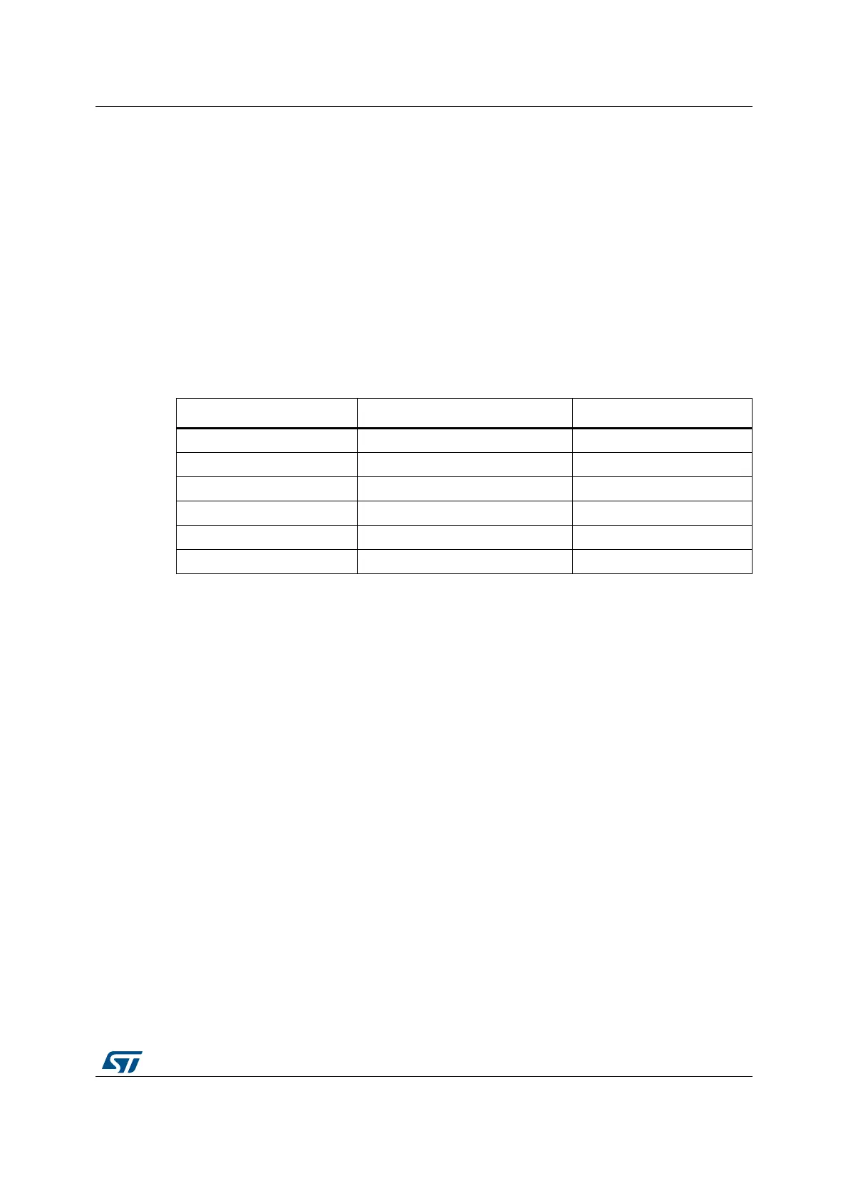
Table 2. STM32F7308-DK board power configuration
CN8 configuration Power connector Voltage
ST-LINK CN1 5 V
USB_STLINK CN1 5 V
E5V CN3 5 V
E5V CN12 7 V-12 V => 5 V
USB_HS CN19 5 V
USB_FS CN18 5 V