Hardware layout and configuration UM2469
22/59 UM2469 Rev 1
7.16 Buttons and LEDs
The black button B2 located LCD side is the reset of the microcontroller STM32F730I8K6.
The blue button B1 located LCD side is available to be used as a digital input or as alternate
function wake-up. When the button is pressed the logic state is 1, otherwise the logic state is
0.
Three LEDs located on the LCD side are available for the user. The LEDs are LD1 Arduino
(blue), LD5 User 1 (red) and LD6 User 2 (green).To light a LED a low-logic state 0 should be
written in the corresponding GPIO.
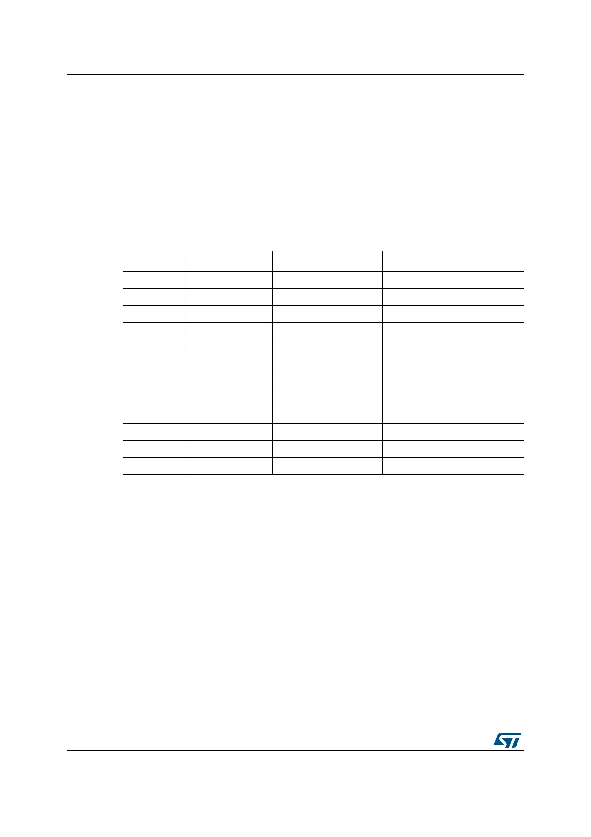
Table 3 gives the assignment of control ports to the LED indicators.
Table 3. Control port assignment
Reference Color Name Comment
B1 BLUE USER Alternate function Wake-up
B2 BLACK RESET -
LD1 BLUE ARDUINO PA5
LD2 RED 5 V Power -
LD3 RED Fault Power Current upper than 625 mA
LD4 RED/GREEN ST-LINK COM Green during communication
LD5 RED USER1 PA7
LD6 GREEN USER2 PB1
LD7 RED USB OTG HS OVCR PH10
LD8 GREEN V
BUS
USB HS PB13
LD9 RED USB OTG FS OVCR PB10
LD10 GREEN V
BUS
USB FS PA9