Fanout board UM2469
54/59 UM2469 Rev 1
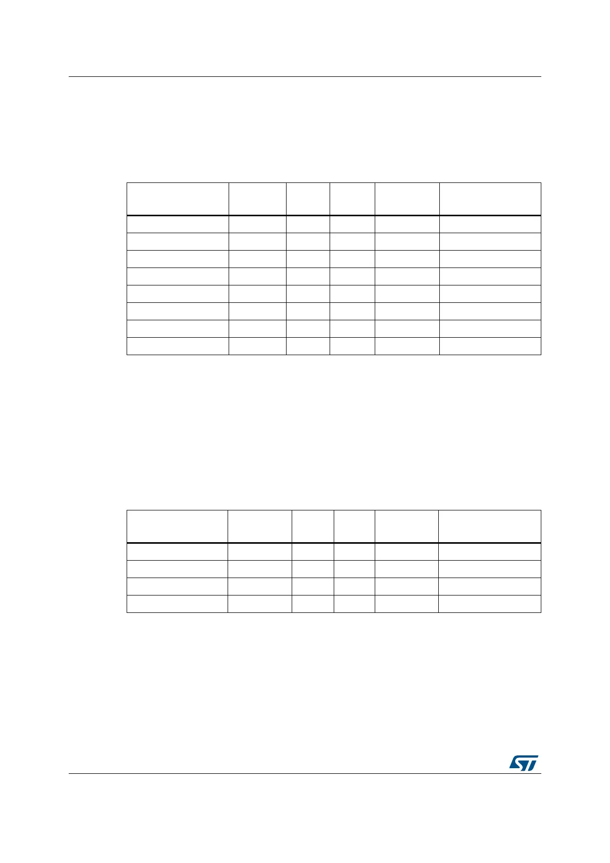
D.1 MikroElektronika mikroBUS™ compatible connector
(Fanout CN10 and CN11)
The mikroBUS™ compatible connector is 2.54" pitch with a pair of 1x8-pin female
connectors.
Table 19 below shows the definition of the pins.
The mikroBUS™ pinout assignment is available at the: http://mikroe.com website.
D.2 ESP-01 Wi-Fi board compatible connector
The ESP-01 Wi-Fi
®
board connector is 2.54 pitch with 2x4-pin female connectors. Table 20
shows the definition of the pins.
Table 19. Description of the mikroBUS
™
connector pins
STMod+ connector
CN11 number
Function of
mikroBUS
Pin
number
Pin
number
Function of
mikroBUS
STMod+ connector
CN10 number
STMod+#13-ADC
(1)
1. Exclusive use: Arduino or STMod+.
AN 1 1 PWM STMod+#14-PWM
(1)
STMod+#12-RST RST 2 2 INT STMod+#11-INT
STMod+#1-NSS CS 3 3 RX STMod+#3-RX
STMod+#4-SCK SCK 4 4 TX STMod+#2-TX
STMod+#9-MISOs MISO 5 5 SCL STMod+#7-SCL
(2)
2. Shared with Arduino.
STMod+#8-MOSIs MOSI 6 6 SDA STMod+#10-SDA
(2)
- +3.3 V 7 7 +5 V -
-GND88GND -
Table 20. Description of the ESP-01 Wi-Fi board connector pins
STMod+ connector
number
Function of
ESP-01
Pin
number
Pin
number
Function of
ESP-01
STMod+ connector
number
- GND 1 8 TXD STMod+#3-RX
STMod+#14 GPIO2 2 7 CH_PD STMod+#13
STMod+#11 GPIO0 3 6 RST STMod+#12-RST
STMod+#2-TX RXD 4 5 V
CC
-