UM2469 Rev 1 25/59
UM2469 Connectors
58
8.3.1 Pmod™ connector P2
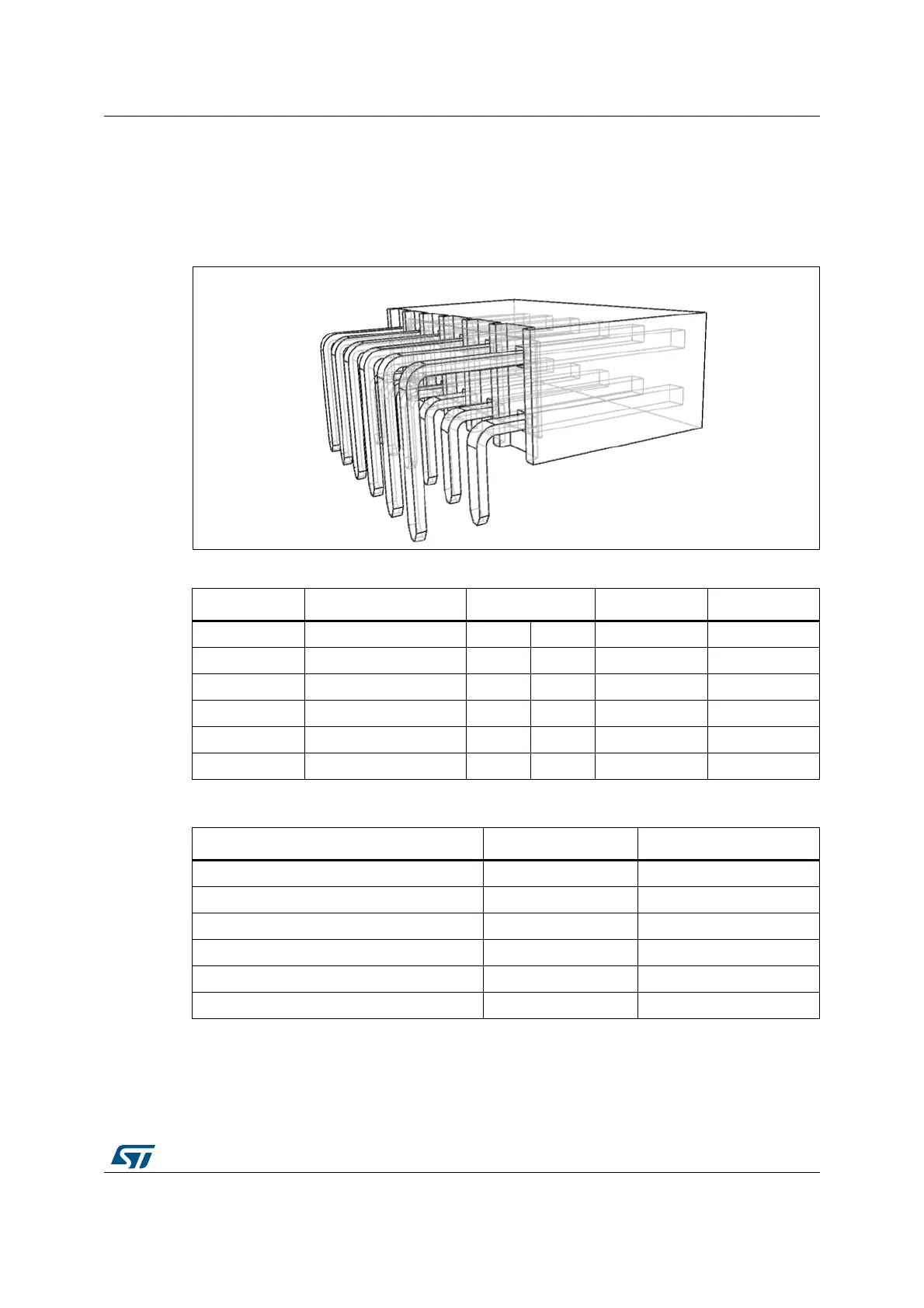
Pmod™ connector is 2x6 pins with 2.54 mm pitch and right-angle female connector. Samtec
SSW-106-02-F-D-RA is selected for Pmod™ connector (second source is available: ATOM
FH254206C-1600).
Figure 14. Pmod™: Samtec SSW connector (P2)
Refer to Section Appendix C: Pmod™ and STMod+ schematic table to find more
information about Pmod™ pins.
Table 6. GPIO assignment for Pmod™ pins
I/O Name Pin number Name I/O
PI0 / PF9 NSS2 / CTS7 1 7 INT PB11
PI3 / PF7 MOSI2p / TX7 2 8 RESET PF11
PI2 / PF6 MISO2p / RX7 3 9 GPIO0 PG12
PI1 / PF8 SCK2 / RTS7 4 10 GPIO1 PH2
GND 5 11 GND
3.3 V 6 12 3.3 V
Table 7. Pmod™: SPI or UART configuration selection
Pin name Pmod™ SPI Pmod™ UART
PMOD_SEL_0 (PH15) 0 1
PMOD_SEL_1 (PI10) 0 1
PMOD#1 NSS CTS
PMOD#2 MOSIp TX
PMOD#3 MISOp RX
PMOD#4 SCK RTS