Connectors UM2469
24/59 UM2469 Rev 1
8.3 Pmod™ and STMod+ connectors P2 and P1
On the STM32F7308-DK board, Pmod™ and STMod+ connectors are providing flexibility in
small form factor applications.
Based on existing Pmod™ Digilent standard popular in connectivity, the STM32F7308-DK
board is supporting the Pmod™ type 2A and 4A on P2 connector.
STMod+ P1 connector uses Pmod™ signals with extended SPI and spare I/Os for different
peripheral expansion. The related STM32F730I8K6 I/Os for Pmod™ and STMod+ function
are listed in
Table 18: STMod+ connector signals.
Refer to Section Appendix C: Pmod™ and STMod+ schematic table to find more
information about Pmod™ and STMod+ pins. Refer to Section Appendix D: Fanout board to
find more information about STMod+ compatible Fanout board.
The user must select the different configurations using PMOD_SEL_0 (PH15) and
PMOD_SEL_1 (PI10) to control the STG3692QTR (U20). This quad analog S.P.D.T. (Single
Pole Dual Throw) allows to connect Pmod™ and STMod+: either to UART or to SPI or to
both in case of STMod+.
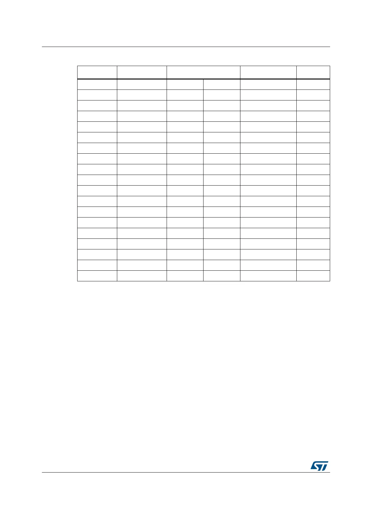
Table 5. GPIO assignment for Arduino pins
I/O Name Pin number Name I/O
- - - CN11.10 SCL2 PH4
(1)
1. Shared between Arduino and STMod+.
- - - CN11.9 SDA2 PH5
(1)
- - - CN11.8 V
REF+
-
- - - CN11.7 GND -
- NC CN12.1 CN11.6 SCK1 PA5
- 3.3 V CN12.2 CN11.5 MISO1 PB4
- NRST CN12.3 CN11.4 MOSI1 PB5
- 3.3 V CN12.4 CN11.3 NSS1 PA1
- 5 V CN12.5 CN11.2 TIM12_CH1 PH6
- GND CN12.6 CN11.1 GPIO PE4
- GND CN12.7 - - -
-V
IN
CN12.8 CN13.8 GPIO PE3
- - - CN13.7 TIM9_CH2 PE6
PA6 ADC1_IN6 CN15.1 CN13.6 TIM3_CH3
(2)
PB0
PA4 ADC1_IN4 CN15.2 CN13.5 GPIO PH3
PC4
(2)
2. Exclusive use: Arduino or STMod+.
ADC1_IN14 CN15.3 CN13.4 TIM9_CH1 PE5
PF10 ADC3_IN8 CN15.4 CN13.3 GPIO PC5
PC0 ADC1_IN10 CN15.5 CN13.2 TX2 PA2
PC1 ADC1_IN11 CN15.6 CN13.1 RX2 PA3