Pmod™ and STMod+ schematic table UM2469
52/59 UM2469 Rev 1
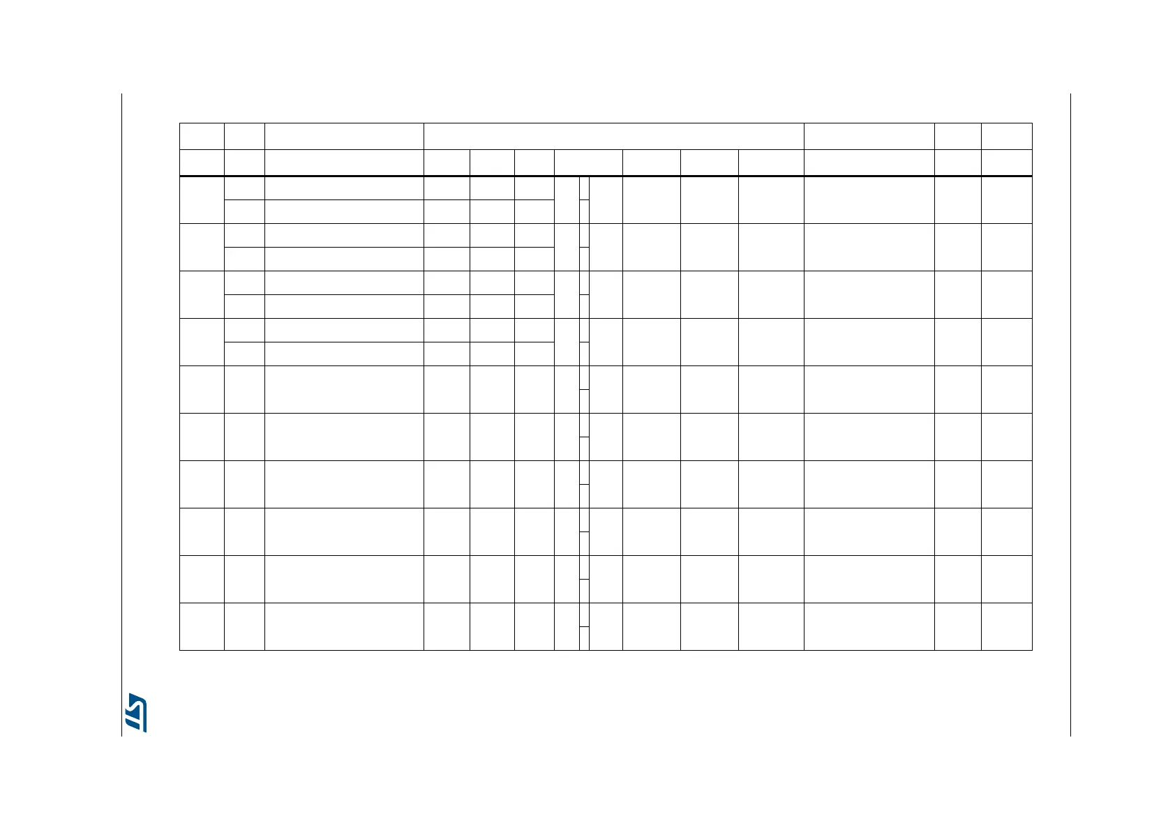
Table 18. STMod+ connector signals
- - - STMod+ - - -
ARD PMOD Some other AF Basic SW Pin Pin number Pin N/A Basic Some other AF PMOD ARD
-
CTS MOSI5/[ADC3.7]/T14.1 CTS7 PI10=1 PF9
1 11 PB11 - INT SDA2/RX3/T2.4 INT -
NSS T5.4 NSS2 PI10=0 PI0
-
TX SCK5/[ADC3.5]/T11.1 TX7 PH15=1 PF7
2 12 PF11 - RST MOSI5 RST -
MOSI T8.8ETR MOSI2p PH15=0 PI3
-
RX NSS5/[ADC3.4]/T10.1 RX7 PH15=1 PF6
3 13 PA4 - ADC/DAC
(1)
NSS1/NSS3/CK2/[ADC2.4]/
[DACOUT1.1]
GPIO
(PG12)
ADC
(1)
MISO T8.4 MISO2p PH15=0 PI2
-
RTS MISO5/[ADC3.6]/T13.1 RTS7 PI10=1 PF8
414PB0 - PWM
(1)
CTS4/[ADC1.8]/[ADC2.8]/
T1.2N/T3.3/T8.2N
GPIO
(PH2)
PWM
(1)
SCK T8.BKIN2 SCK2 PI10=0 PI1
- - - GND - GND 5 15 +5 V - +5 V - - -
- - - +5 V - +5 V 6 16 GND - GND - - -
SCL2
(2)
--SCL2
(2)
- PH4 7 17 PH13 - GPIO TX4/TXCAN1/T8.1N - -
- - [ADC1.13]/[ADC2.13]/[ADC3.13] MOSI2s - PC3 8 18 PH14 - GPIO RX4/RXCAN1/T8.2N - -
- - [ADC1.12]/[ADC2.12]/[ADC3.12] MISO2s - PC2 9 19 PA15 - GPIO
NSS1/NSS3/RTS4/T2.1/T2.
2_ETR
--
SDA2
(2)
-NSS5SDA2
(2)
- PH5 10 20 PC11 - GPIO MISO3/RX3/RX4 - -
1. Exclusive use: Arduino or STMod+.
2. Shared between Arduino and STMod+.