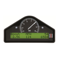
STACK ST8100 Display System Error! Main Document Only.Chapter 5. Installing the Display System
Users Guide 23
SwitchesSwitches
The four switches are used to control the functions of the Display System.
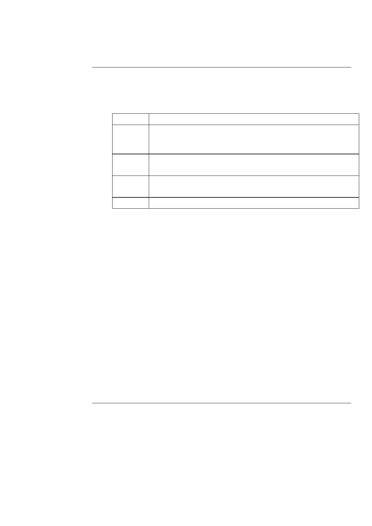
The normal functions of the four switches are:
Switch Functions
Switch 1 1. Show Peak Values
2. Freeze speed on "HOLD" display (optional Corner Speed feature
only)
Switch 2 1. Clear Alarm
2. Show Last Alarm
Switch 3 1. Change Display Layer
2. Clear Alarm
Switch 4 Manual Lap Marker
You can install the switches in any convenient location. When installing
the switches, you should take account of the following considerations:
• The cable for each switch is approximately 400mm in length from the
19-way military connector.
• It is important that the driver is able to reach Switch 3 easily in order
to change the display and clear warning messages after alarms. This
switch is normally fitted on the steering wheel.
• If the driver is also going to enter lap markers manually, Switch 4
should ideally be fitted on the steering wheel.
• When you configure the system, you use Switches 1 to 4 for selecting
the parameters and setting their values. These switches should be
installed so that you can reach them easily when you are viewing the
digital display.