
C
crystal91Sep 18, 2025
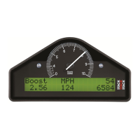
Why does my Stack ST8100 speed reading stop working after a short time?
- BbakerseanSep 18, 2025
If your Stack Monitor speed reading dies after a short time, the ambient temperature might be too high. Shield the sensor from radiated heat from brakes and bearings. Insulate the sensor from conducted heat with fibre washers, and duct cooling air around the sensor.
